Circuit Breaker with Integrated Power Measurement

a circuit breaker and integrated technology, applied in the direction of thermoelectric instruments, electric devices, instruments, etc., can solve the problem of difficulty in identifying where energy is being consumed in a specific building or within a structur

Active Publication Date: 2016-04-14
DRAKO DEAN
View PDF8 Cites 3 Cited by
  • Summary
  • Abstract
  • Description
  • Claims
  • Application Information

AI Technical Summary

Problems solved by technology

Everyone wants to save money but it is difficult to identify where energy is being cons

Method used


Image

  • Circuit Breaker with Integrated Power Measurement
  • Circuit Breaker with Integrated Power Measurement
  • Circuit Breaker with Integrated Power Measurement

Examples


Embodiment Construction

[0025]Conventional circuit protectors are concerned with preventing current or voltage outside of a threshold or beyond an extent of time. But energy consumption or conservation objectives are not served by these essentially binary triggers.

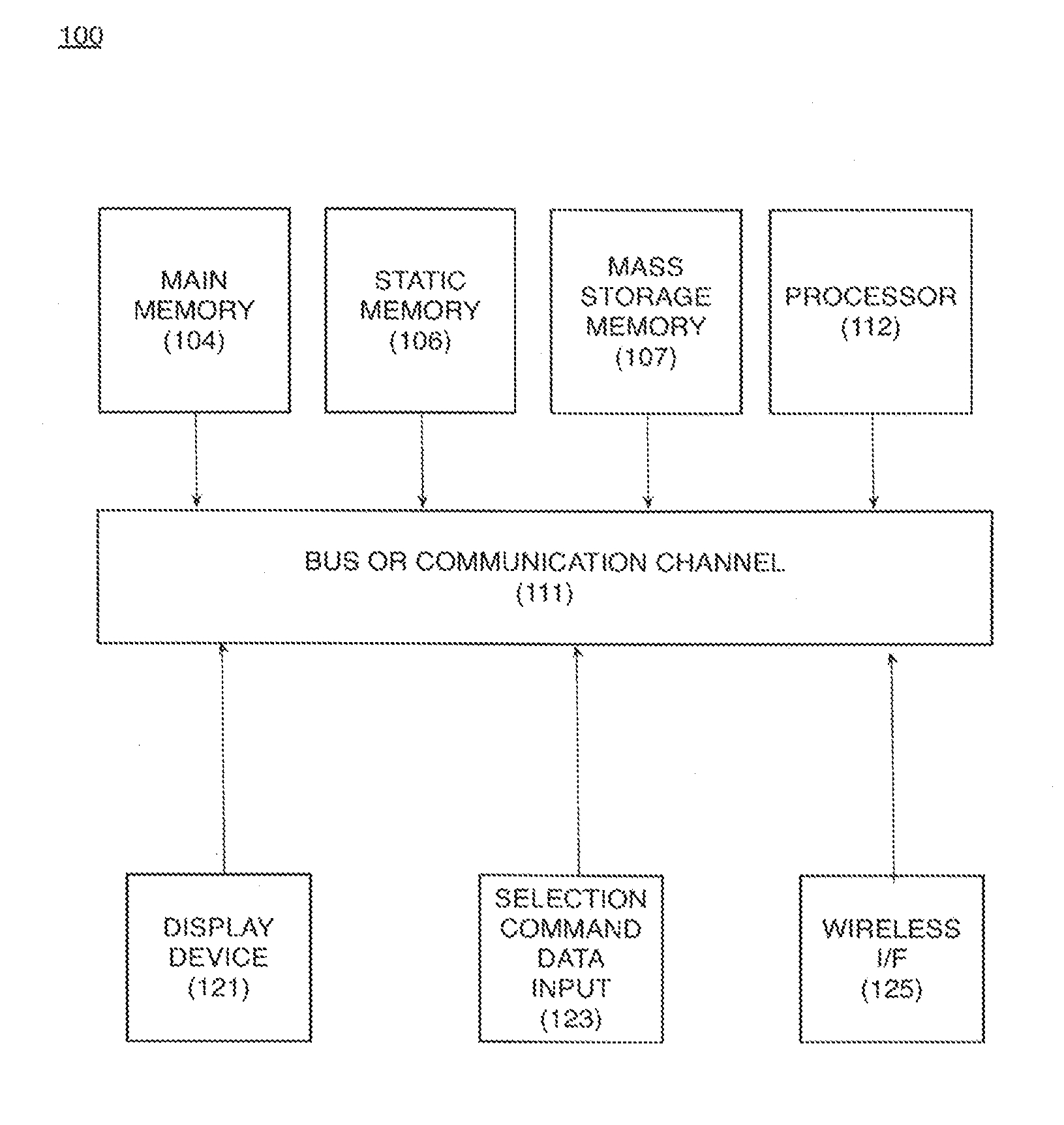
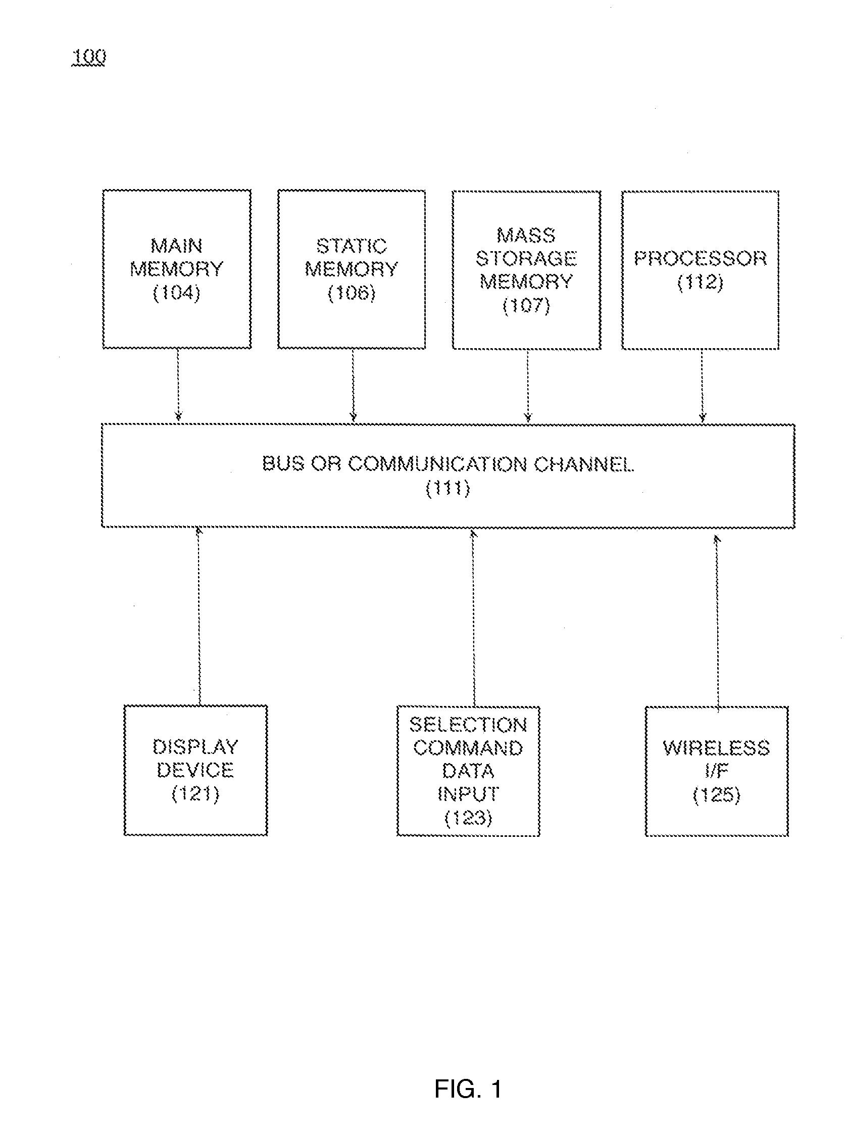
[0026]Applicant discloses a solution which can be embodied as a little IC chip in the circuit breaker.

[0027]The important part is to have the VOLTMETER that will tell us amperage.

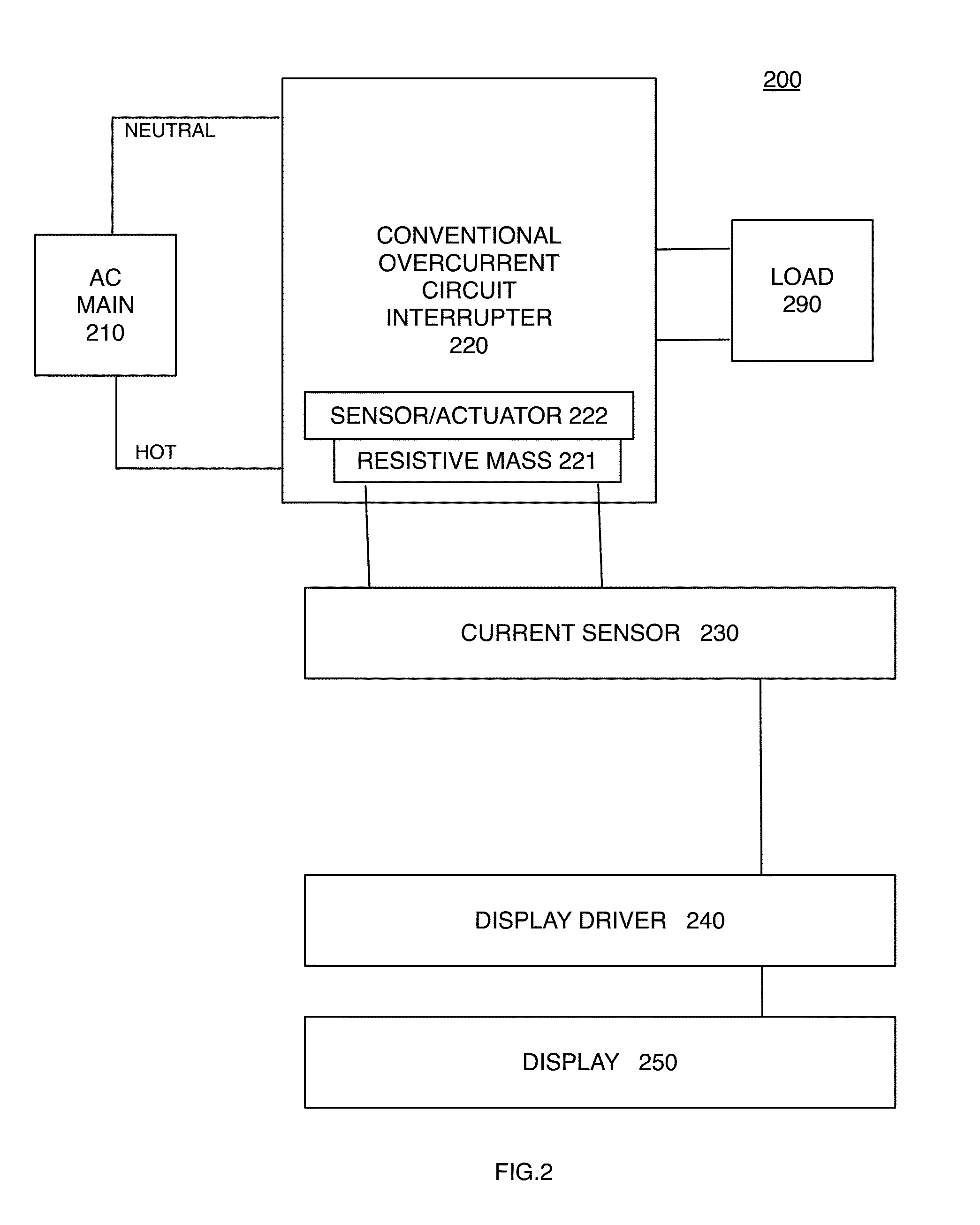
[0028]In one embodiment, Amperage is measured by measuring VOLTAGE drop across a very Low Value resistor. This very low value resistor can be a component in the circuit breaker or can use the bimetal portion of the circuit breaker as a resistor.

[0029]As is known, because CURRENT (AMPS)=VOLTAGE / RESISTANCE we can determine the amount of current by a measurement of potential or voltage.

[0030]Once we know the current (in our little micro controller) that drives the display, in an embodiment, a little LCD display.

[0031]The display is calibrated to transform the measured volta...


PUM


Abstract

A circuit apparatus measures, records, transmits, and displays actual and estimated power consumption in a branch circuit of an electrical distribution system. The apparatus includes a display driver coupled to one or more current sensors which derives or estimates power consumption from measured current. The accuracy of power consumption is improved by additional measurement of actual supplied voltage. A plurality of current sensors determine differential current to provide ground fault interruption to a desired range of precision. A store enables display of surge and average current measurements and power measurements in addition to immediate results.

Description

CROSS-REFERENCES TO RELATED APPLICATIONS[0001]This application benefits from its related provisional application 62062961 filing date 13 Oct. 2014.STATEMENT REGARDING FEDERALLY SPONSORED RESEARCH OR DEVELOPMENT[0002]Not ApplicableTHE NAMES OF THE PARTIES TO A JOINT RESEARCH AGREEMENT[0003]Not ApplicableINCORPORATION-BY-REFERENCE OF MATERIAL SUBMITTED ON A COMPACT DISK OR AS A TEXT FILE VIA THE OFFICE ELECTRONIC FILING SYSTEM (EFS-WEB)[0004]Not ApplicableSTATEMENT REGARDING PRIOR DISCLOSURES BY THE INVENTOR OR A JOINT INVENTOR[0005]Not ApplicableBACKGROUND OF THE INVENTION[0006]1. Technical Field[0007]Class 200 electricity: circuit makers and circuit breakers with power measurement.[0008]2. Description of the Related Art[0009]Power consumption has become a concern for both industry and homeowners. Everyone wants to save money but it is difficult to identify where energy is being consumed in a specific building or within a structure and see the effect of making changes.[0010]Conventio...

Claims


Application Information

Patent Timeline
IPC IPC(8): G01R21/00H02H3/08G01R15/20G01R19/165G01R17/00
CPCG01R21/00G01R19/165H02H3/08G01R15/202G01R17/00G01R1/203G01R19/10G01R31/3277H02H3/162H02H5/047
Inventor DRAKO, DEAN
Owner DRAKO DEAN
Why Eureka
Try Eureka