Method for transmitting and receiving data between MPU and memory in PLC

Active Publication Date: 2016-04-14
LSIS CO LTD
View PDF4 Cites 0 Cited by
  • Summary
  • Abstract
  • Description
  • Claims
  • Application Information

AI Technical Summary

Benefits of technology

The invention allows for data to be transmitted and received between a multi-chip unit (MPU) and a memory in a power line communication (PLC) system without any loss of data. This is achieved by using a 1-bit address as an input to an OR gate, which activates a data input buffer. This method ensures that data can be transferred between the MPU and memory without any data loss, even if devices with different operating voltages are added.

Problems solved by technology

Concomitant with requirement of high speed operation for semiconductor devices such as MPUs (Micro Processing Units), memories and logic ICs, an operating frequency thereto is also required to increase whereby power consumption is also increased.
The increased power consumption can result in heated ICs and energy wastes, which brings forth a trend of speedy transmission and receipt of data and realization of low operating voltages.
Meantime, voltage levels of ICs used in PLCs (Programmable Logic Controllers) widely used for controlling automation facilities at industrial sites are 1.2V, 3.3V and 5V, which means that operating voltages are different, such that methods for transmitting and receiving data between devices have surfaced as new issues.
However, disadvantages have occurred where one memory is shared by MPUs having different operating voltages, as the MPUs are used for each function such as basic operation, communication and position control for performance enhancement.
When one memory is used by the MPUs having different operating voltages as noted above, a problem occurs where an MPU having a different operating voltage from that of a memory cannot have a smooth transmission / reception of data with the memory, although an MPU having a same operating voltage as that of the memory can normally perform the transmission / reception of data with the memory.

Method used


Image

  • Method for transmitting and receiving data between MPU and memory in PLC
  • Method for transmitting and receiving data between MPU and memory in PLC
  • Method for transmitting and receiving data between MPU and memory in PLC

Examples


Embodiment Construction

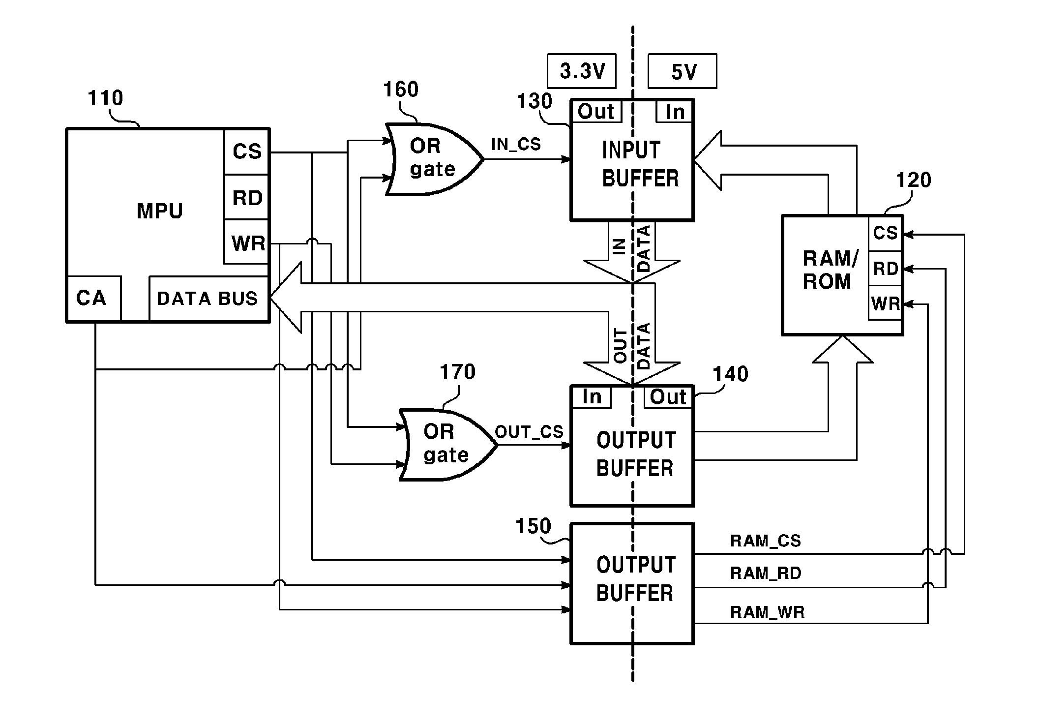
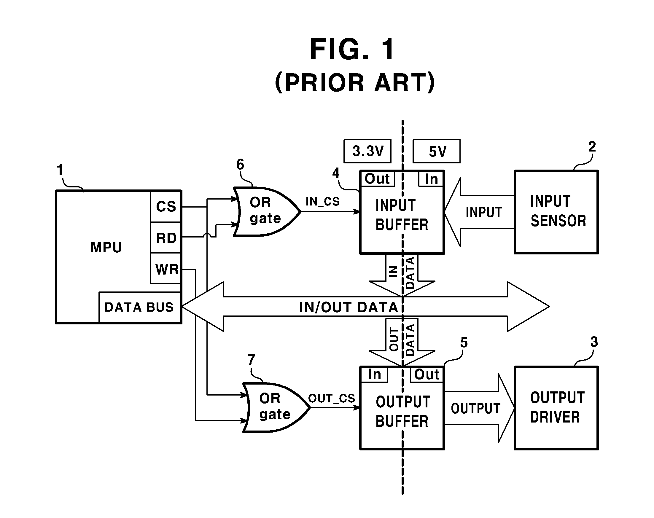
[0040]Various exemplary embodiments will be described more fully hereinafter with reference to the accompanying drawings, in which some exemplary embodiments are shown.

[0041]Advantages and features of the present disclosure may be understood more readily by reference to the following detailed description of exemplary embodiments and the accompanying drawings. Thus, the present disclosure is not limited to the exemplary embodiments which will be described below, but may be implemented in other forms.

[0042]The particular embodiments disclosed herein are illustrative only, as the invention may be modified and practiced in different but equivalent manners apparent to those skilled in the art having the benefit of the teachings herein. The present disclosure may, however, be embodied in many different forms and should not be construed as limited to the embodiments set forth herein. Rather, these embodiments are provided so that this disclosure will be thorough and complete, and will full...


PUM


Abstract

A method for transmitting and receiving data between an MPU and a memory operating in mutually different operating voltages in PLC is proposed, the method including: outputting, by the MPU, a CS (Chip Select) signal and an address signal in order to read data by approaching to the memory; outputting, by an OR gate, an activation signal for activating a data input buffer by receiving the CS signal and the address signal; outputting, by an access signal output buffer, a memory access signal for operation of the memory by receiving the CS signal and the address signal; outputting, by the memory, data requested by the MPU to the data input buffer by responding to the memory access signal; and outputting, by the data input buffer, the received data to the MPU by receiving the data outputted by the memory.

Description

CROSS-REFERENCE TO RELATED APPLICATION[0001]Pursuant to 35 U.S.C. §119(a), this application claims the benefit of earlier filing date and right of priority to Korean Patent Application No. 10-2014-0137572, filed on Oct. 13, 2014, the contents of which are all hereby incorporated by reference herein in its entirety.BACKGROUND OF THE DISCLOSURE[0002]1. Field[0003]The teachings in accordance with the exemplary embodiments of this present disclosure generally relate to a method for transmitting and receiving data between an MPU and a memory that operate in mutually different operating voltages in PLC.[0004]2. Background[0005]Concomitant with requirement of high speed operation for semiconductor devices such as MPUs (Micro Processing Units), memories and logic ICs, an operating frequency thereto is also required to increase whereby power consumption is also increased. The increased power consumption can result in heated ICs and energy wastes, which brings forth a trend of speedy transmis...

Claims


Application Information

Patent Timeline
IPC IPC(8): G05B19/05G11C7/10
CPCG05B19/05G11C7/1057G11C7/1063G11C7/10G11C7/1084
Inventor PARK, JO DONG
Owner LSIS CO LTD
Why Eureka
Try Eureka