Rebar Tying Machine

Active Publication Date: 2016-04-21
TAIZHOU XINDALU ELECTRONICS TECH
View PDF1 Cites 30 Cited by
  • Summary
  • Abstract
  • Description
  • Claims
  • Application Information

AI Technical Summary

Benefits of technology

[0019]First, since the anti-rotation fixing pin axially moves in the advance/retreat locating slot and slides in the peripheral direction in the rotating cam slot, the positioning of the steel wire winding assembly is more accurate, and the safety factor of the overall operation is improved by the advance/retreat locating slot and the rotating cam slot; since the axial extension of a side wall of the rotating cam slot along a sleeve forms a chamfer structure, the rebar tying machine is prevented from being jammed, the smooth operation of the winding mechanism is ensured, the wear to the parts is reduced, and the service life is prolonged.
[0020]Second, in the present invention, as the driving force arms of the large fork and the small fork are increased, it is easier to cut the steel wires off, thereby effectively reducing load of the drive motor and saving power to complete more work under the same battery. In the present invention, since triggers are designed on the large fork and the small fork and against the wire discharge plate, the wire discharge plate has two bearing points which are stressed at the same time, and the whole mechanism is thus stressed more evenly and stably. Since the chute intersected with the wire discharging passage is disposed on the wire discharging block, the wi

Problems solved by technology

The rebar tying machine with such a structure has relatively low stabili

Method used


Image

  • Rebar Tying Machine
  • Rebar Tying Machine
  • Rebar Tying Machine

Examples


embodiment 1

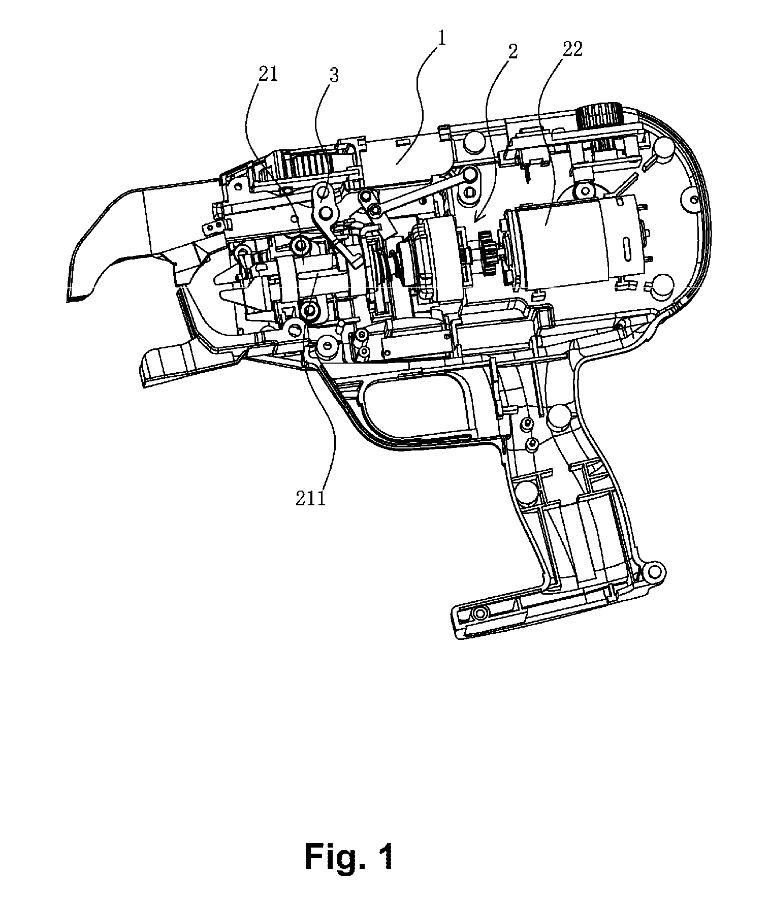
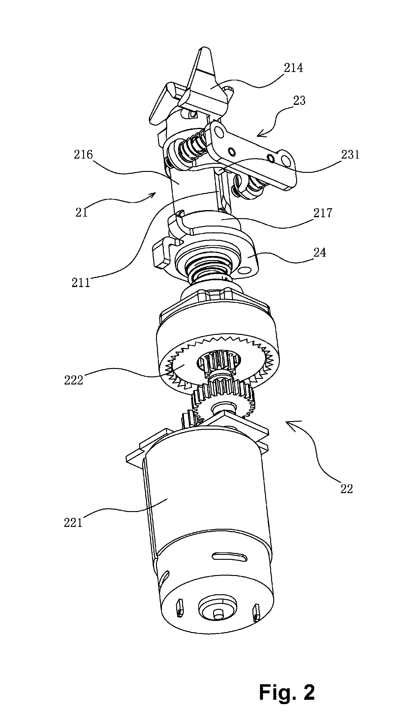
[0052]With reference to FIG. 7, according to the rebar tying machine of the present invention, the locking device 23 further includes a fixing base 232 and a connecting plate 233 mounted on the fixing base 232. The anti-rotation fixing pin 231 is mounted on the connecting plate 233, and a fixing shaft 235 with a resetting spring 234 is disposed on the fixing base 232; and the connecting plate 233 is mounted on the fixing shaft 234. Since the advance / retreat locating slot 211 and the rotating cam slot 212, which are disposed on an outer wall of the sleeve 216, are fitted with the resetting spring 234 on the fixing shaft 235, the jamming caused by the entrance of the dirt is effectively avoided, and the service life of the machine is prolonged.

embodiment 2

[0053]With reference to FIG. 15, according to the rebar tying machine of the present invention, the locking device 23 further includes a pedestal 236 having thereon a hollow protrusion 237 within which the anti-rotation fixing pin 231 is disposed. A resetting spring 234 is provided between the anti-rotation fixing pin 231 and the protrusion 237; and a reinforcing rib 238 is formed between the pedestal 236 and the protrusion 237 to reinforce the connection strength. Since the advance / retreat locating slot 211 and the rotating cam slot 212 are fitted with each other by the anti-rotation fixing pin therein, when in operation, the winding assembly can automatically rotate and stop rotating in accordance with specific conditions, thereby improving the safety factor of the overall operation.

[0054]With reference to FIG. 11 to FIG. 14, according to the rebar tying machine of the present invention, the steel wire cutting-off mechanism 3 includes a transmission device 31, a wire discharging b...


PUM


Abstract

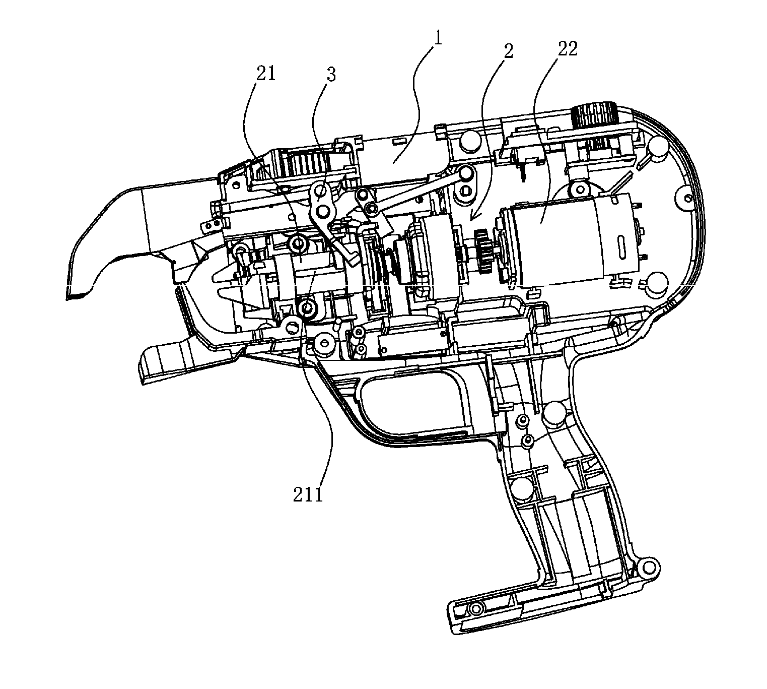
A rebar tying machine comprising a tying machine main body (1) and a steel wire winding assembly (2) mounted in the main body, a steel wire cutting off mechanism (3) is further mounted in the main body and comprises a transmission device (31) and a wire discharging block (32), the steel wire winding assembly comprises a winding mechanism (21), a driving device (22) for driving the winding mechanism and a locking device for locking the winding mechanism, an advance/retreat locating slot (211) and a rotating cam slot which are communicated with each other are arranged on the winding mechanism, an anti-rotation fixing pin (231) in the locking device moves axially in the advance/retreat locating slot, and the anti-rotation fixed pin slides in the rotating cam slot along the circumferential direction. The rebar tying machine has the advantageous effect that: the anti-rotation fixed pin moves axially in the advance/retreat locating slot and slides in the rotating cam slot along the circumferential direction, and the sidewall of the rotating cam slot extends along the axial direction of a sleeve (216) to form a chamfer structure, thus preventing the tying machine from locking and further ensuring the working smoothness of the winding mechanism.

Description

CLAIM OF PCT APPLICATION, 35 U.S.C. §371[0001]The present invention is a national stage entry from a PCT application, pursuant to the provision of 35 U.S.C. section 371 et seq., based upon the application filed by the same inventor in China, having PCT application number PCT / CN2013 / 001410 filed on Nov. 18, 2013.FIELD AND BACKGROUND OF THE INVENTION[0002]A rebar tying machine includes: a tying thread feeding mechanism, configured to feed a tying thread for a steel wire reeled on a steel wire reel and wind the tying thread on the rebar; and a tying thread twisting mechanism, configured to twist the tying thread wound on the rebar. The tying thread feeding mechanism and the tying thread twisting mechanism work in sequence through the operation of a starter, in order to complete a series of tying actions. For example, Chinese Invention Patent 200910203087.1, publicized on Nov. 25, 2009 under CN101586399, disclosed a rebar tying machine, including: a main sleeve having a hook pivotally m...

Claims


Application Information

Patent Timeline
IPC IPC(8): E04G21/12B65B13/28B65B13/04
CPCE04G21/123B65B13/285B65B13/04
Inventor LU, FUJUN
Owner TAIZHOU XINDALU ELECTRONICS TECH
Why Eureka
Try Eureka