
Control apparatus for fuel injection valve and mehod thereof

Active Publication Date: 2016-04-21
TOYOTA JIDOSHA KK
View PDF2 Cites 8 Cited by
  • Summary
  • Abstract
  • Description
  • Claims
  • Application Information

AI Technical Summary

Benefits of technology

The invention relates to a control apparatus for a fuel injection valve and a method thereof. The technical effect of the invention is to provide a precise calculation of the injection standby period by accurately measuring the fuel pressure and taking into account the increase in fuel pressure over a period of time. This results in improved control precision for the fuel injection valve and allows for better performance of the engine overall.

Problems solved by technology

With this estimation method, therefore, it cannot easily be said that the estimation precision of the injection standby period is high.

Method used


Image

  • Control apparatus for fuel injection valve and mehod thereof
  • Control apparatus for fuel injection valve and mehod thereof
  • Control apparatus for fuel injection valve and mehod thereof

Examples


Embodiment Construction

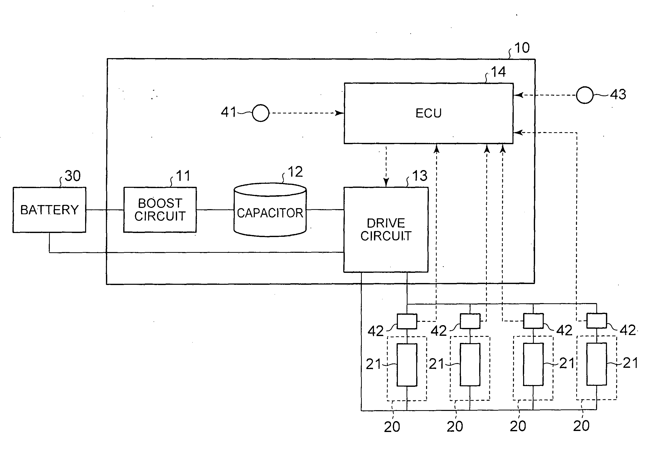
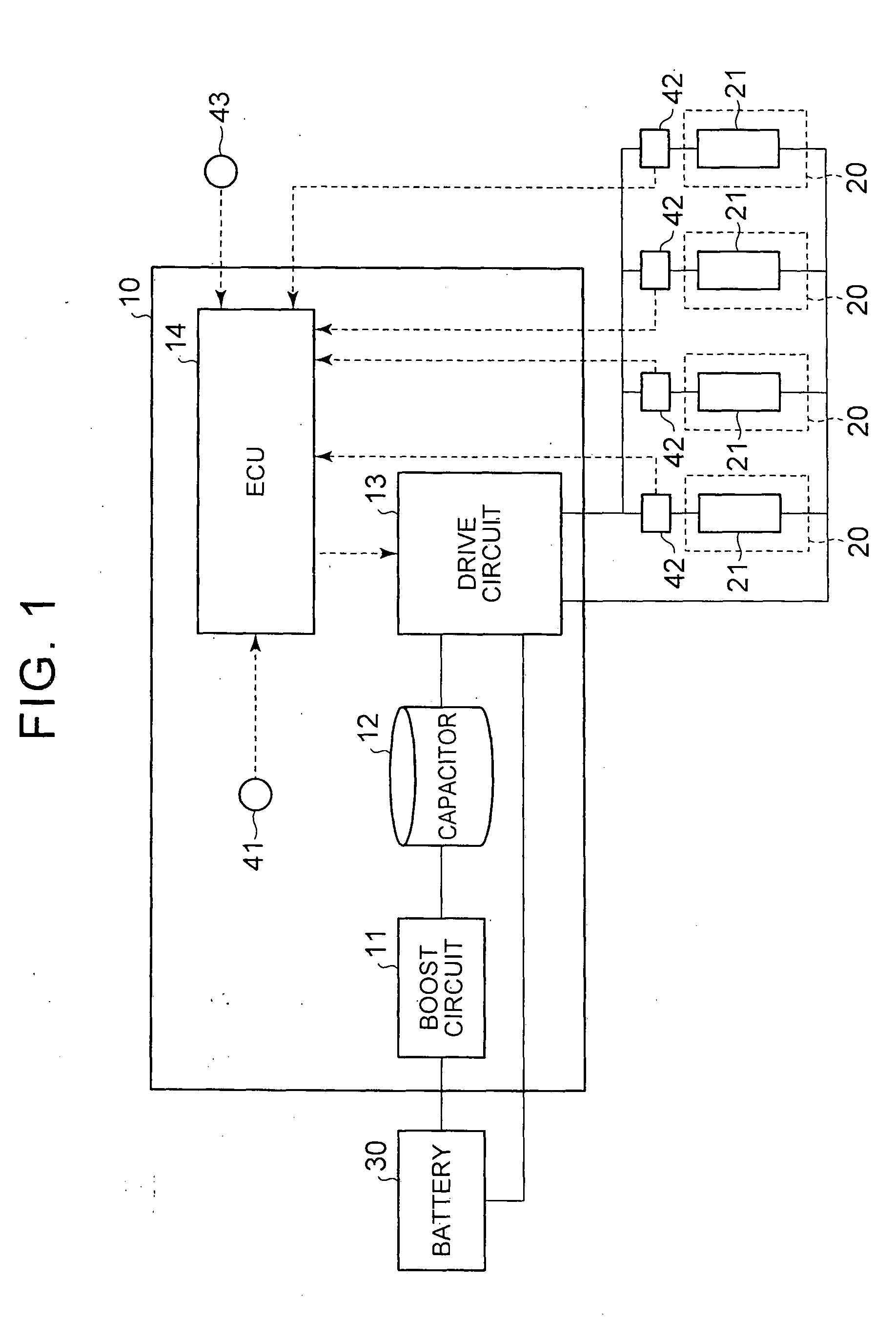
[0057]Referring to FIGS. 1 to 16, a specific embodiment of a control apparatus for a fuel injection valve, which operates a fuel injection valve provided in an internal combustion engine (an engine) to open and close, will be described below. FIG. 1 shows a control apparatus 10 for a fuel injection valve according to this embodiment, and a plurality of fuel injection valves 20 (four here) controlled by the control apparatus 10. The fuel injection valves 20 are respectively constituted by injection valves for direct injection that inject fuel directly into a combustion chamber of the internal combustion engine (the engine).

[0058]As shown in FIG. 1, the control apparatus 10 includes a boost circuit 11 that boosts a voltage of a battery 30 provided in a vehicle, a capacitor 12 charged with the voltage boosted by the boost circuit 11, and a drive circuit 13 serving as a drive control unit. The drive circuit 13 drives the fuel injection valves 20 using the capacitor 12 and the battery 30...


PUM


Abstract

An electronic control unit that calculates an injection standby period, which is a period from an energization start point of the solenoid to a point at which the fuel injection valve opens, and adjusts an energization period of the solenoid in accordance with the calculated injection standby period. The electronic control unit of the control apparatus for a fuel injection valve then measures a reference fall detection period, which is a period from the energization start point to a reference fall detection point, and sets the injection standby period to be longer as the reference fall detection period is longer. Here, the reference fall detection point is a point at which the excitation current detected by the current detection circuit falls below a reference current value, which is smaller than a peak current value, while the excitation current decreases after reaching the peak current value.

Description

BACKGROUND OF THE INVENTION[0001]1. Field of the Invention[0002]The invention relates to a control apparatus for a fuel injection valve, which performs opening and closing operations on a fuel injection valve provided in an internal combustion engine (an engine), and a method thereof.[0003]2. Description of Related Art[0004]An energization period of a fuel injection valve during a single fuel injection is separated into an opening period for opening the injection valve and a holding period for holding the injection valve in an open condition. During the opening period, power is supplied to a solenoid of the fuel injection valve from a capacitor capable of applying a higher voltage than a battery. During the opening period, therefore, an excitation current flowing in the solenoid is increased. In this case, an electromagnetic force generated by the fuel injection valve grows gradually stronger until the injection valve opens. When the excitation current reaches a peak current value s...

Claims


Application Information

Patent Timeline
IPC IPC(8): F02D41/40F02M63/00
CPCF02M63/0017F02D41/40F02D41/20F02D41/2467H01F7/1844F02D2041/2055F02D2041/2058F02D2200/0602
Inventor NAKANO, TOMOHIROMURASE, EIJIKANEKO, RIHITO
Owner TOYOTA JIDOSHA KK
Features
  • Generate Ideas
  • Intellectual Property
  • Life Sciences
  • Materials
  • Tech Scout
  • Unparalleled Data Quality
  • Higher Quality Content
  • 60% Fewer Hallucinations
Learn More