Check patentability & draft patents in minutes with Patsnap Eureka AI!

Articulated Drive Shaft

a technology of drive shaft and mud motor, which is applied in the direction of drilling pipes, mechanical equipment, couplings, etc., can solve the problems of time-consuming processes, limited torque output of drive shafts of mud motors currently utilized, and insufficient bending of drills hit on the lower end of pipes to achieve the effect of avoiding bending

Inactive Publication Date: 2016-04-21
KLX ENERGY SERVICES
View PDF4 Cites 6 Cited by
  • Summary
  • Abstract
  • Description
  • Claims
  • Application Information

AI Technical Summary

Benefits of technology

The patent describes a drive shaft assembly used in drilling equipment. The assembly includes a flow diverter which helps to direct fluid from the mud motor to the drilling bit. The assembly also includes other components such as ball seats and face sealing rings to improve the sealing of the joint and prevent lubricants from leaking or drilling fluids from entering the joint. The invention helps to improve the performance and efficiency of drilling equipment.

Problems solved by technology

In the drilling of directional wellbores, conventional drilling methods of rotating a drill hit on the lower end of a pipe suing are inadequate to create the curved portion the borehole.
The drive shafts of mud motors currently utilized are limited in the amount of torque which can be outputted, in many cases being unable to apply sufficient strength to transmit the torque required to advance a wellbore.
Such processes are time consuming and incur additional cost in man hours.
As well, pushing traditional mud motors to their maximum torque capacity causes considerable stress on its moveable components and requires input of excessive amounts of fluid through the components and seals of the mud motor.
Operating mud motors at such high stress makes them subject to regular breakdown due to excessive wear and tear on the motor components and, in particular, the motor pressure seals which are vital for maintaining fluid pressure.

Method used


Image

  • Articulated Drive Shaft
  • Articulated Drive Shaft
  • Articulated Drive Shaft

Examples


first embodiment

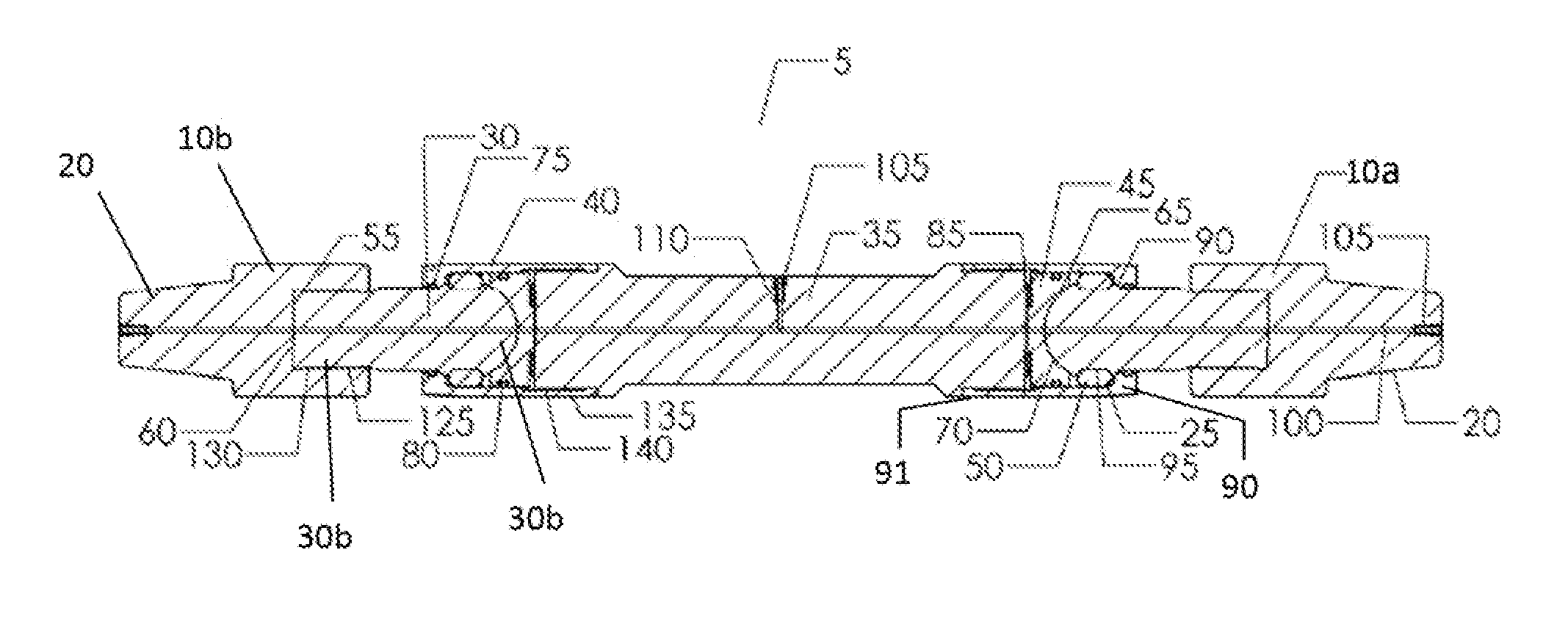
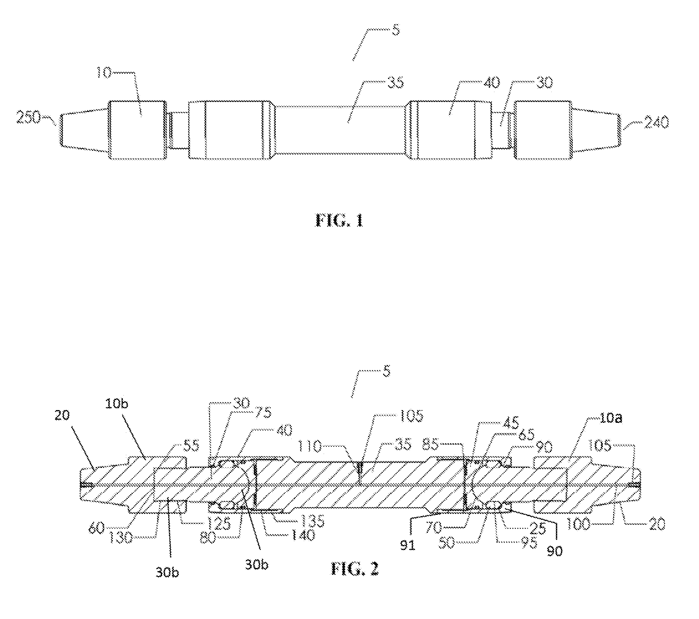
[0031]FIGS. 1 and 2 show an articulated drive shaft (5). The articulated drive shaft (5) has a central elongated member known as a “driven” (35) positioned between upper and lower cylindrical members, each known as a “driver” (10a &10b). This combination provides an upper cylindrical driver (10a) at upper end (240) of the drive shaft (5) and a lower cylindrical driver (10b) at lower end (250) of the drive shaft (5). Driver (10a) at upper end (240) of drive shaft (5) is threadedly attached to a rotor of a mud motor or other rotational device by means of threaded connection (20). Driver (10b) at lower end (250) of drive shaft (5) is threadedly attached to a pipe sub or to a drill bit by means of threaded connection (20).

[0032]Cylindrical drivers (10a &10b) at the upper end (240) and lower end (250) each have a ball member (30) having a spherical end (30a) and an elongated shaft (30b). Elongated shall (30b) has external attachment threads (125) which allow for threaded attachment to cy...

second embodiment

[0040]the articulated drive shaft (5) is shown in FIG. 6. As shown in FIG. 6, the articulated drive shaft (5) has a compensating driven member (180) having a central bore (170) for holding lubricants (not pictured) and opposing driven pistons (160). Drilling fluids surrounding the drive shaft (5) will enter holes (175) in pressure compensating driven (180) and the pressure from the entering drilling fluids will force pistons (160) to move outwardly, which will then force the lubricants (not pictured) through lubrication passages (100) and lubricate the joints. The fluid pressure on pistons (160) will maintain positive pressure upon the lubricant, making certain the joint remains full of lubricant (not pictured). Pistons (160) utilize a piston sealing element (165) to create a seal between piston (160) and the central bore of driven (180). This piston sealing element (165) prevents lubricants (not pictured) from escaping the bore (170) and also prevents drilling fluid from entering t...


PUM


Abstract

An articulated drive shaft for a downhole mud motor is provided for transmission of torque and thrust loads from one member to another mainly comprising a driven member, ball members, a plurality of rollers, ball socket members and cylindrical driver members. The drive shaft is allowed to transmit torque and thrust loads through a given angular range between the axes of members on each end of the assembly. Several sealing means for retaining lubricants within the joints are provided while maintaining the mud motor's ability to articulate within borehole. A flow diverter may also be incorporated into the drive shaft to provide a means for fluid passage through the chive shaft.

Description

PRIORITY[0001]This application claims priority to U.S. provisional application Serial No. 62 / 066,607 filed Oct. 21, 2014 entitled “Articulated Drive Shaft and Method”, the entire content of which is incorporated b reference.FIELD OF THE INVENTION[0002]This invention pertains to downhole equipment for oil and gas wells. More particularly, it pertains to an articulated drive shaft for a downhole mud motor and, more particularly, this invention relates to an articulated drive shaft for transferring torque and thrust loads from the rotor to the mud motor mandrel.BACKGROUND OF THE INVENTION[0003]In the drilling of directional wellbores, conventional drilling methods of rotating a drill hit on the lower end of a pipe suing are inadequate to create the curved portion the borehole. Thus, mud motors which include a bent section generally up to 3 degrees, are utilized to drill this curved portion.[0004]These mud motors consist of three major components a power section consisting of a rotor an...

Claims


Application Information

Patent Timeline
IPC IPC(8): F16D3/221E21B17/20
CPCE21B17/20F16D3/221E21B4/02E21B7/068E21B17/05F16D3/848F16D2300/06F16D3/223
Inventor BAUDOIN, TOBY SCOTT
Owner KLX ENERGY SERVICES
Features
  • R&D
  • Intellectual Property
  • Life Sciences
  • Materials
  • Tech Scout
  • Unparalleled Data Quality
  • Higher Quality Content
  • 60% Fewer Hallucinations
Learn More