Asset-condition monitoring system

a monitoring system and monitoring system technology, applied in the field of asset condition monitoring system, can solve the problems of cumbersome and inconvenient analog user interface used in conventional ultrasonic wall thickness measurement system, subject to corruption/attenuation, other undesirable effects, etc., to achieve easy integration, increase the integrity of data obtained, and impart modularity

Active Publication Date: 2016-04-21
SENSOR NETWORKS
View PDF16 Cites 14 Cited by
  • Summary
  • Abstract
  • Description
  • Claims
  • Application Information

AI Technical Summary

Benefits of technology

[0011]Applicants recognize that the proprietary, analog user interface used in conventional ultrasonic wall thickness measuring systems is cumbersome and inconvenient, and subject to corruption / attenuation and other undesirable effects. To minimize these shortcomings, Applicants recognize that “pushing” the proprietary and analog circuitry as close to the sensors as practical and using a digital bus to interconnect the sensors increases the integrity of the data obtained and imparts modularity by enabling the use of conventional, off-the-shelf user interfaces. In particular, Applicants propose a system comprising a digital bus interconnecting one or more digital sensor interfaces (DSIs), which are proximate to the analog sensors and contain the necessary circuity to convert the analog sensor signals to digital signals and transmit these digital signals on the digital bus. By locating the proprietary interface—i.e., the DSI—as close to the sensors as practical, most of the cabling and signal transmission is digital and non-proprietary, and thus can be readily integrated with off-the-shelf consumer electronic devices such as tablets, smart phones, and laptops without the need for converting / downloading or otherwise manipulating signals.
[0012]Such a system provides for a number of important benefits. For example, in one embodiment, the system of the present invention uses a standard digital, multi-drop communication link, such as RS485 / Modbus, or CANbus, to connect the user interface with the DSIs which in turn are connected to the sensors. The multi-drop bus allows a single multi-pair wire to access multiple sensor and sensor installations reducing cable cost and installation complexity. Furthermore, standard bus / protocol allows DSI and sensor installation to be easily connected to other plant equipment such as DCS (distributed control system) or SCADA (supervisory control and data acquisition) system.
[0013]In one embodiment, the user interface (i.e. tablet or cell phone) comprises digital connectivity via wired means such as USB or wireless means such as Wi-Fi or Cellular communications. This enables the data to be pushed from the user interface via wired or wireless connections. Such connectivity facilitates cloud data storage which may be used as a collection point for the ultrasonic wall thickness data as well as related information about the installation. Examples of related information could be device information such as serial numbers, asset information, GPS coordinates, installation photographs, nominal wall thickness information, wall thickness limits, and 3D asset models. The ability to push data to the cloud also facilitates hosting the system through the Web. A Web-hosted user interface may be used for data display and analysis such that an asset operator can view and analyze its data from any Web connected computer or handheld device. Cloud storage access also provides enhanced visibility to data and can also be advantageous for meeting archiving and reporting requirements. It can further offer the ability to trigger automated alarms when an alarm threshold condition is met. Such alarms could be delivered via email or text message for instance. An additional advantage of cloud storage / computing is the potential for advanced data post processing and analytics.

Problems solved by technology

Applicants recognize that the proprietary, analog user interface used in conventional ultrasonic wall thickness measuring systems is cumbersome and inconvenient, and subject to corruption / attenuation and other undesirable effects.

Method used


Image

  • Asset-condition monitoring system
  • Asset-condition monitoring system
  • Asset-condition monitoring system

Examples


Embodiment Construction

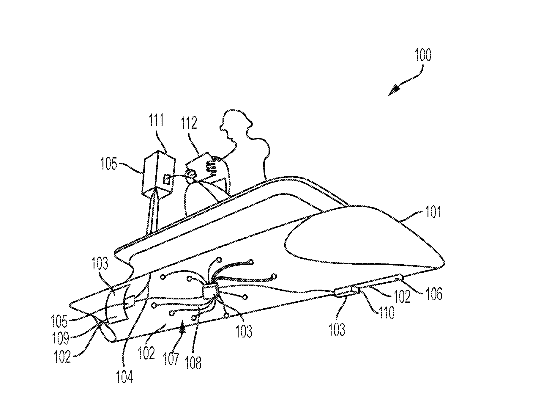
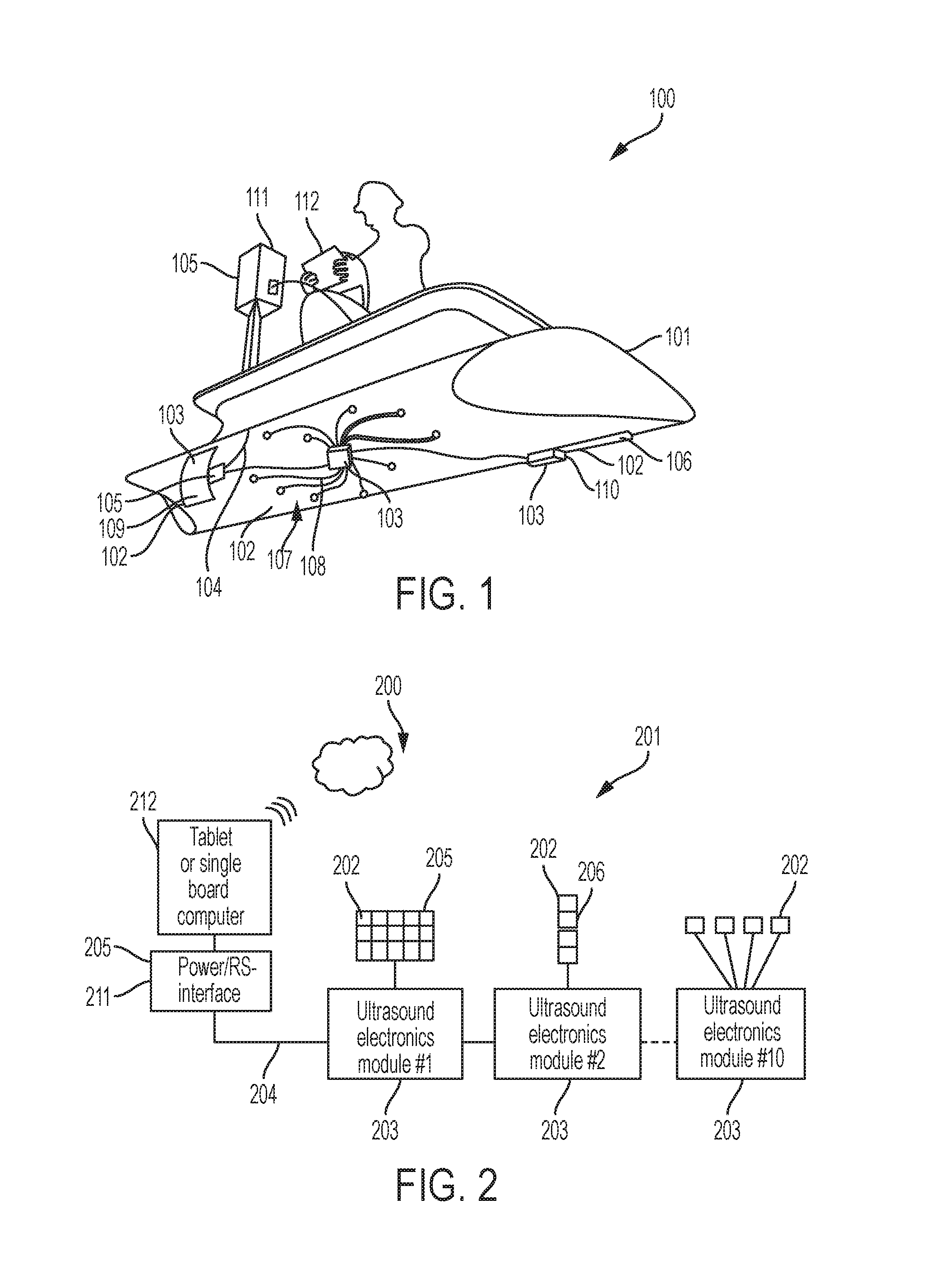
[0029]Referring to FIGS. 1 and 2, a perspective view and schematic view of one embodiment of the ultrasound sensing system 100, 200, respectively, of the present invention is shown. In this embodiment, the system 100, 200 functions to determine wall thickness of a structure 101, and comprises a plurality of ultrasound sensors 102, 202. Each sensor 102, 202 is configured to receive a first electrical signal, transmit an ultrasound signal in response to said first electrical signal, receive a reflected ultrasound signal, and transmit a second electrical signal in response to said reflected ultrasound signal. The first and second electrical signals are analog. The system 100, 200 also comprises at least one digital sensor interface (DSI) 103, 203 to which at least a portion of said sensors 102, 202 are connectable. The DSI is configured to transmit said first electrical signal and receive said second electrical signal, and to generate a time-voltage waveform commonly known as an A-scan...


PUM

PropertyMeasurementUnit
thicknessaaaaaaaaaa
timeaaaaaaaaaa
electrical signalaaaaaaaaaa

Abstract

An ultrasound sensing system for monitoring the condition or integrity of a structure, comprising (a) a plurality of ultrasound sensors, each sensor being configured to receive at least one first electrical signal, transmit an ultrasound signal in response to the first electrical signal, receive at least one reflected ultrasound signal, and transmit a second electrical signal in response to the reflected ultrasound signal, the first and second electrical signals being analog; (b) at least one digital sensor interface (DSI) to which at least a portion of the sensors are connectable, the DSI being configured to transmit the first electrical signal and receive the second electrical signal, and to generate an A-scan signal based on the first and second electrical signals for each sensor, the DSI having circuitry for transmitting a digital signal based directly or indirectly on at least the A-scan signal, the digital signal including an address corresponding to the at least one DSI; (c) a digital bus configured to receive the digital signal from the at least one DSI; (d) a user interface connected to the bus to receive the digital signal; and wherein, in one embodiment, the sensors are mounted semi-permanently on the structure and the DSI is also mounted semi-permanently on or adjacent to the structure being monitored.

Description

CROSS REFERENCE TO RELATED APPLICATIONS[0001]This application claims the benefit of U.S. Provisional Application No. 62 / 058,592, filed Oct. 1, 2014, and U.S. Provisional Application No. 62 / 137,532, filed Mar. 24, 2015, the entire disclosures of which are incorporated herein by reference.FIELD OF INVENTION[0002]The invention relates generally to a system for ultrasonically monitoring the condition and integrity of pipes and / or other structures or assets, such as those used in the oil and gas and power generation industries.BACKGROUND[0003]Wall thickness and the presence of defects such as cracks are important factors in determining the fitness-for-service of structures such as above and below ground pipes and tanks When a pipe is in operation, it can be subject to corrosion and / or erosion due to the content, flow and / or environmental conditions inside or outside of the pipe. Cracks can form and propagate due to the presence of manufacturing defects, creep, thermal cycling, fatigue an...

Claims


Application Information

Patent Timeline
Patent Type & Authority Applications(United States)
IPC IPC(8): G01N29/04H04W4/00G01N29/44H04B11/00H04W4/70
CPCG01N29/043H04B11/00G01N2291/044G01N29/44H04W4/005G01N29/11G01N2291/02854G01N2291/106G01N29/0645G01N2291/015G01N2291/0234G01N2291/0258H04W4/70
Inventor PELLEGRINO, BRUCE A.BARSHINGER, JAMES
Owner SENSOR NETWORKS
Why Eureka
Try Eureka