Check patentability & draft patents in minutes with Patsnap Eureka AI!

System and method for debugging firmware/software by generating trace data

Active Publication Date: 2016-04-21
INSYDE SOFTWARE
View PDF4 Cites 9 Cited by
  • Summary
  • Abstract
  • Description
  • Claims
  • Application Information

AI Technical Summary

Benefits of technology

The present invention provides a system, method, recording medium, and computer program product for debugging firmware / software by generating trace data. This system can perform bug tracing on embedded systems like BIOS or Android without changing their program code. The system allows users to control branch trace functions in real time and analyze data in real time. The system records the power-on procedure of the embedded system and uses limited storage space. Overall, this technology allows for more efficient and effective debugging of embedded systems.

Problems solved by technology

One difficulty of the modular software is that, each module may have different writers or be provided by different objects having different program agreements.

Method used


Image

  • System and method for debugging firmware/software by generating trace data
  • System and method for debugging firmware/software by generating trace data
  • System and method for debugging firmware/software by generating trace data

Examples


first embodiment

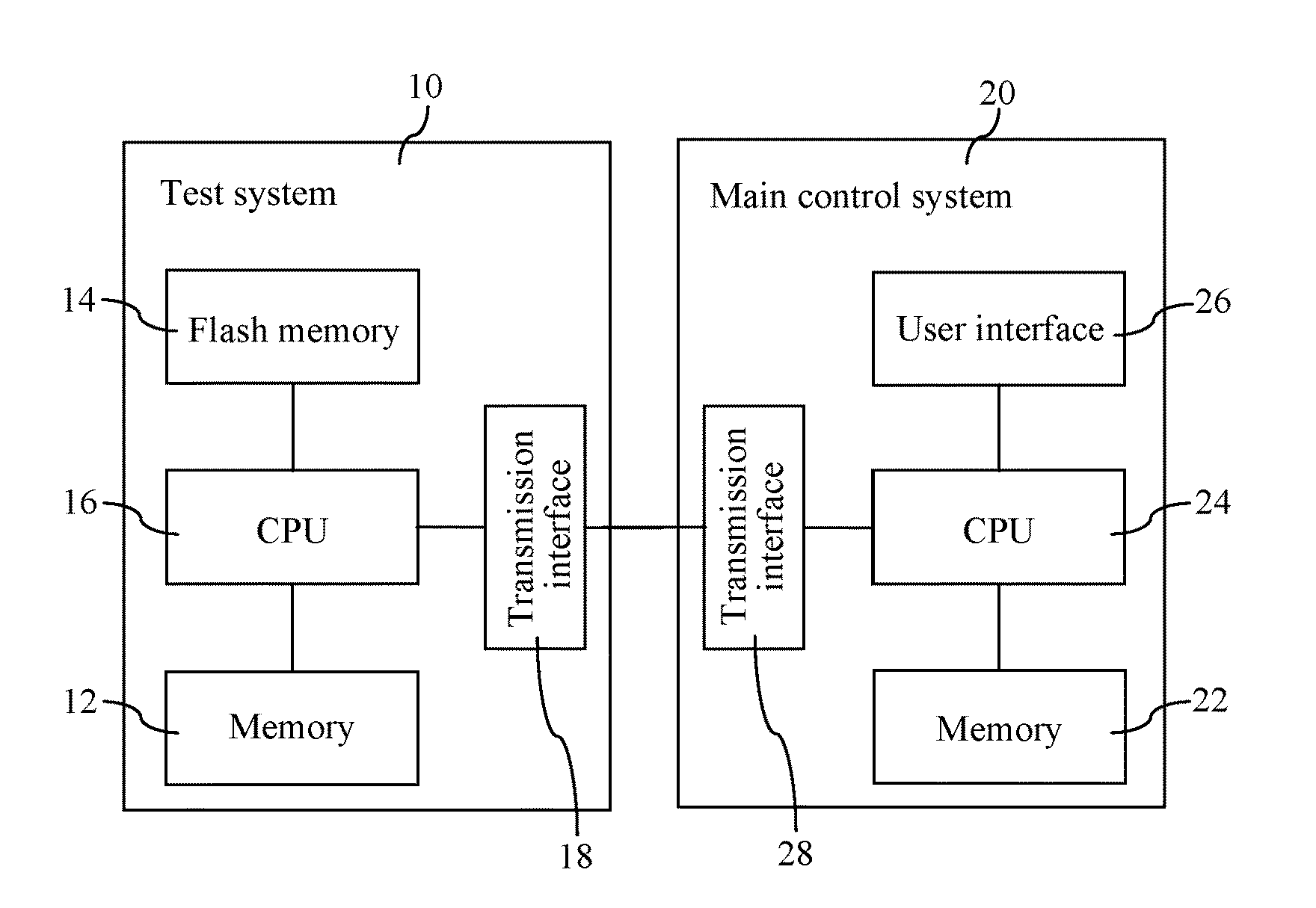
[0043]FIG. 1 is a block diagram of a system for debugging firmware / software by generating trace data according to the present invention. In FIG. 1, the system for debugging firmware / software by generating trace data includes a test system 10 and a main control system 20.

[0044]The test system 10 includes a memory 12, a flash memory 14, a CPU 16, and a transmission interface 18. The main control system 20 includes a memory 22, a CPU 24, a user interface 26, and a transmission interface 28.

[0045]In the test system 10, the flash memory 14 stores the BIOS. In a power-on stage, without needing to change program code of a module of the BIOS, the CPU 16 runs a debug engine to configure an area (not shown) of the memory 12 used for temporary storage, traces and records a power-on procedure of the BIOS by using limited storage space, connects the main control system 20 to the test system 10, and records a load address and a branch instruction execution record set into the area for temporary s...

second embodiment

[0068]FIG. 7 is a block diagram of a test system for debugging firmware / software by generating trace data according to the present invention. In FIG. 7, the test system 70 for debugging firmware / software by generating trace data includes a memory 72, a flash memory 74, a CPU 76 and a user interface 78.

[0069]The flash memory 74 stores the BIOS; the memory 72 stores a program debug symbol table and source program code of the BIOS, wherein the program debug symbol table is generated when the source program code is compiled.

[0070]When the test system 70 is in a power-on stage, the CPU 76 runs a debug module to configure an area (not shown) of the memory 72 used for temporary storage, traces and records a power-on procedure of the BIOS by using limited storage space, and records a load address and a branch instruction execution record set of an interested tested module into the area for temporary storage, wherein the load address is an address of the tested module, which is loaded in the...


PUM


Abstract

A method for debugging firmware / software by generating trace data includes the following steps: running a debug module in a power-on stage in a test system, to record a load address and a branch instruction execution record set of a tested module into an area for temporary storage; accessing, by an analyzer, in an operating system stage in the area for temporary storage, the load address and the branch instruction execution record set and accessing a program debug symbol table, where the program debug symbol table is generated when source program code is compiled; and finding, by the analyzer, an original source file, a function name, and line numbers of executed codes from the program debug symbol table according to the load address and the branch instruction execution record set to generate an analysis report that includes a program execution path and a program code coverage.

Description

BACKGROUND[0001]1. Technical Field[0002]The present invention relates to the field of computer technologies, and in particular, to a system and a method for debugging firmware / software by generating trace data, a recording medium, and a computer program product.[0003]2. Related Art[0004]Modern software is written into a system in a modular manner. Each module has a specific function, and has a specific interface for interacting with another module. In this manner, each module may be written and separately tested, so that multiple developers work in parallel in a relatively large software system. Modular software also favorably allows an existing module to be combined into multiple larger systems. One difficulty of the modular software is that, each module may have different writers or be provided by different objects having different program agreements. Therefore, it is an indispensable work to test interaction between software modules to ensure that the behavior of a software syste...

Claims


Application Information

Patent Timeline
IPC IPC(8): G06F11/36
CPCG06F11/3664G06F11/3636
Inventor CHENG, YING CHIN
Owner INSYDE SOFTWARE
Features
  • R&D
  • Intellectual Property
  • Life Sciences
  • Materials
  • Tech Scout
  • Unparalleled Data Quality
  • Higher Quality Content
  • 60% Fewer Hallucinations
Learn More