
Magnetic field structures, field generators, navigation and imaging for untethered robotic device enabled medical procedure

a robotic device and magnetic field technology, applied in the field of robotic field structures, can solve the problems of non-disease-related surgery increasing the risk of sepsis, scarring, blood loss and decreased motor function, and undesired accumulation of materials and materials

Inactive Publication Date: 2016-04-21
SUZARA VINCENT
View PDF6 Cites 65 Cited by
  • Summary
  • Abstract
  • Description
  • Claims
  • Application Information

AI Technical Summary

Benefits of technology

This patent describes a system and method for generating magnetic fields to position and energize medical devices. The system consists of multiple magnetic field generators that face each other and produce magnetic fields that meet in a center point. These magnetic fields are then shielded and contained in an enclosure. The system can also be positioned around a fixed point using articulation frames and supports. The generated magnetic fields are rotated in opposite directions. The technical effects of this system include the ability to accurately position medical devices and improve their energy performance.

Problems solved by technology

A wide variety of medical procedures are currently performed with undesirable and unavoidable effects on the patient that include damage to healthy tissue during surgery and distribution of therapeutic substances (drugs, antibodies, vaccines and regenerative cells) to sites other than the intended target.
Non-disease related surgery increases the risk of sepsis, scarring, blood loss and decreased motor function.
Non-specific therapeutic side effects include impacts on metabolic organs and nervous tissue, undesired accumulation in the liver, fatty tissue and digestive tract, and widespread dilution in the circulatory system.
Many of these effects are unavoidable.
In addition, tools, implants and related devices commonly require large tethers, such as the surgeon's hands, catheters, clamps, etc., for manipulation.
For most bio-therapeutics, encapsulation, localization and site-specific delivery are limited because related technology is in its infancy.
The latter remains non-optimal due to non-specific substance distribution.
Unfortunately, procedures that accomplish those effector functions also negative impact healthy tissue.
In addition, some avoidable or ameliorable diseases remain because procedures to address them result in collateral damage disproportionate to the amount of benefit.
The shared causative factor is that medical technology is currently disadvantaged by an inability to limit operator, electro-mechanical, and biochemical procedures to necessary effector functions.
The pharmaco-kinetic (PK) question of why an effect or lack thereto occurred often depends on radioactive and other complex and expensive tracing to determine PK / PD.
In all cases, monitoring of encapsulated payload is not possible except when using magnetic resonance or ultrasonic imaging (MRI, USI) of capsules modified for compatibility with such systems, modifications thereto potentially detrimental to the biotherapeutic payload.
Current endoscopic robots are relatively large and not applicable to vessels and vascular tissue smaller than about 1 cm in diameter.
Thus, protocols for cardiovascular, lymphatic and metabolic organs with more narrow vascularization are not possible with current endoscopic robot technology.
Interest in [mm] scale drone aircraft and gyroscopes, systems also sharing many qualities with ideal medical robots, is high; however, rapid translation of these technologies is hampered by their incompatibility with current MRI and USI systems that only perform diagnosis.
Moreover, current MRI technology is incompatible with most robots as well as many implants because of their electrical sensitivity and magnetic susceptibility.

Method used


Image

  • Magnetic field structures, field generators, navigation and imaging for untethered robotic device enabled medical procedure
  • Magnetic field structures, field generators, navigation and imaging for untethered robotic device enabled medical procedure
  • Magnetic field structures, field generators, navigation and imaging for untethered robotic device enabled medical procedure

Examples


Embodiment Construction

.”

BRIEF DESCRIPTION OF THE DRAWINGS

[0017]Features, aspects, and embodiments are described in conjunction with the attached drawings, in which:

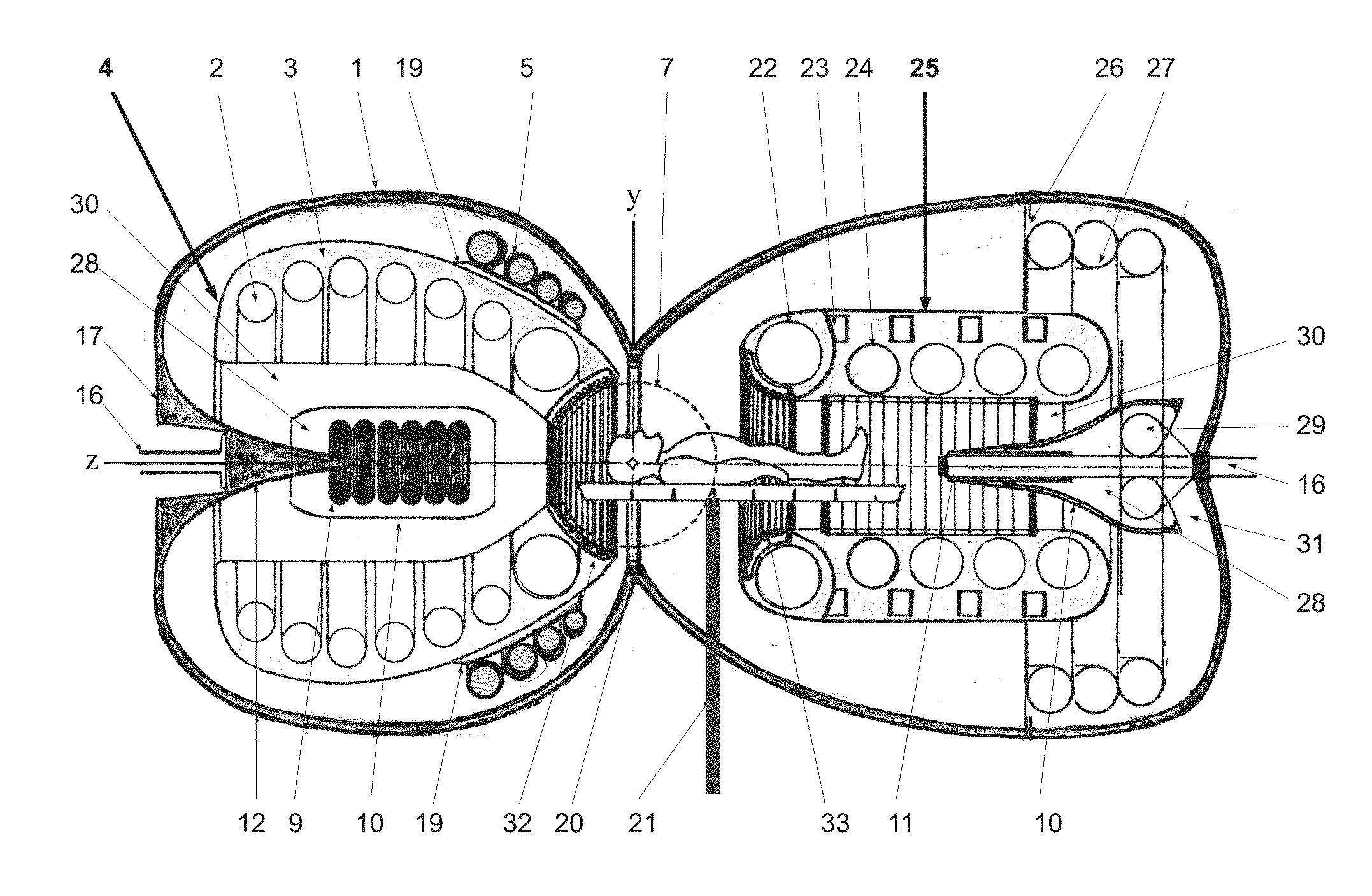
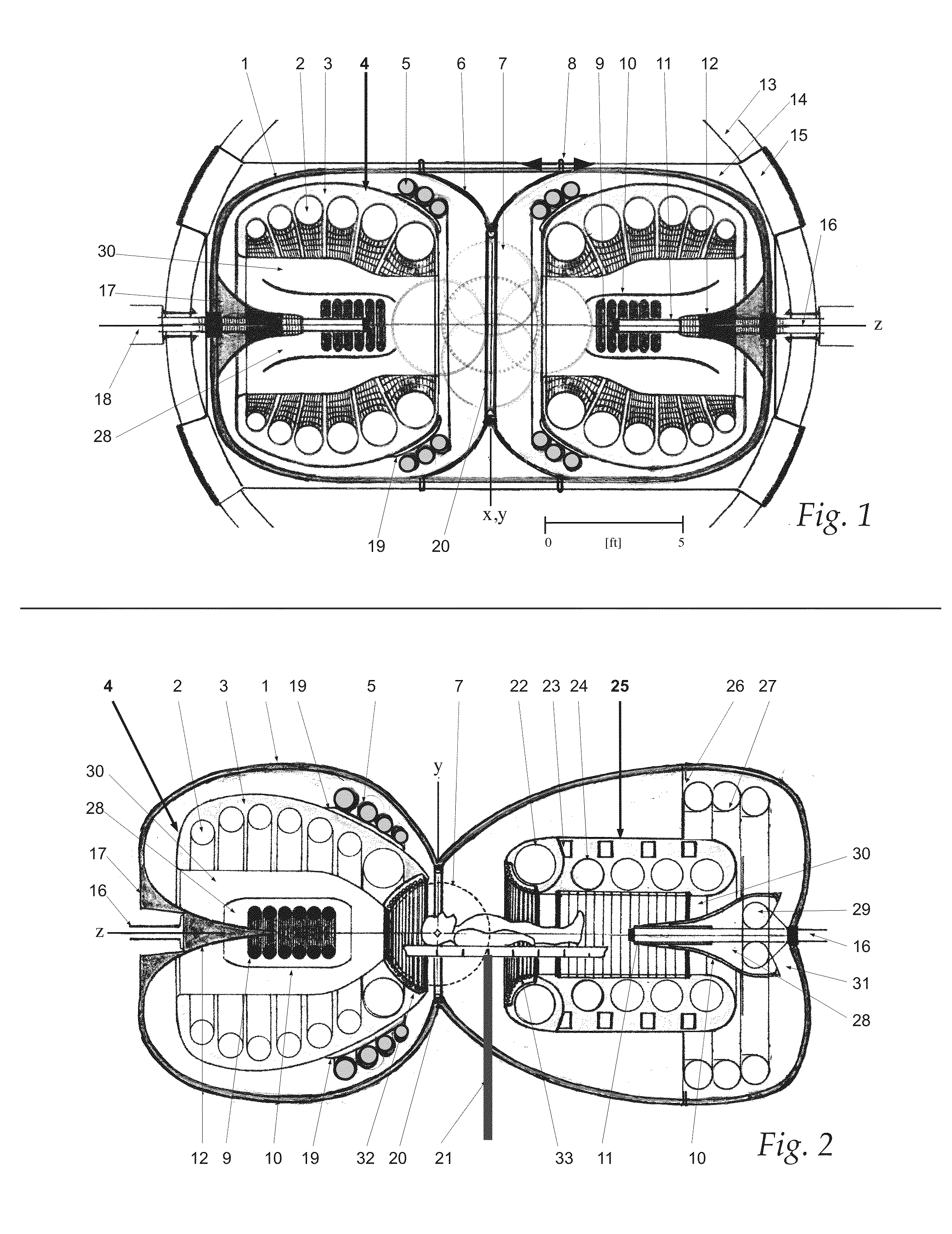
[0018]FIG. 1 is a diagram of a diagnostic-therapeutic apparatus comprising two coaxial, co-facing equivalent magnetic field generators disposed about a central therapeutic space large enough to accommodate a person in accordance with one embodiment.

[0019]FIG. 2 is a diagram illustrating a neurological diagnostic-therapeutic apparatus comprising two coaxial, co-facing field generators disposed about a central therapeutic space in accordance with one embodiment.

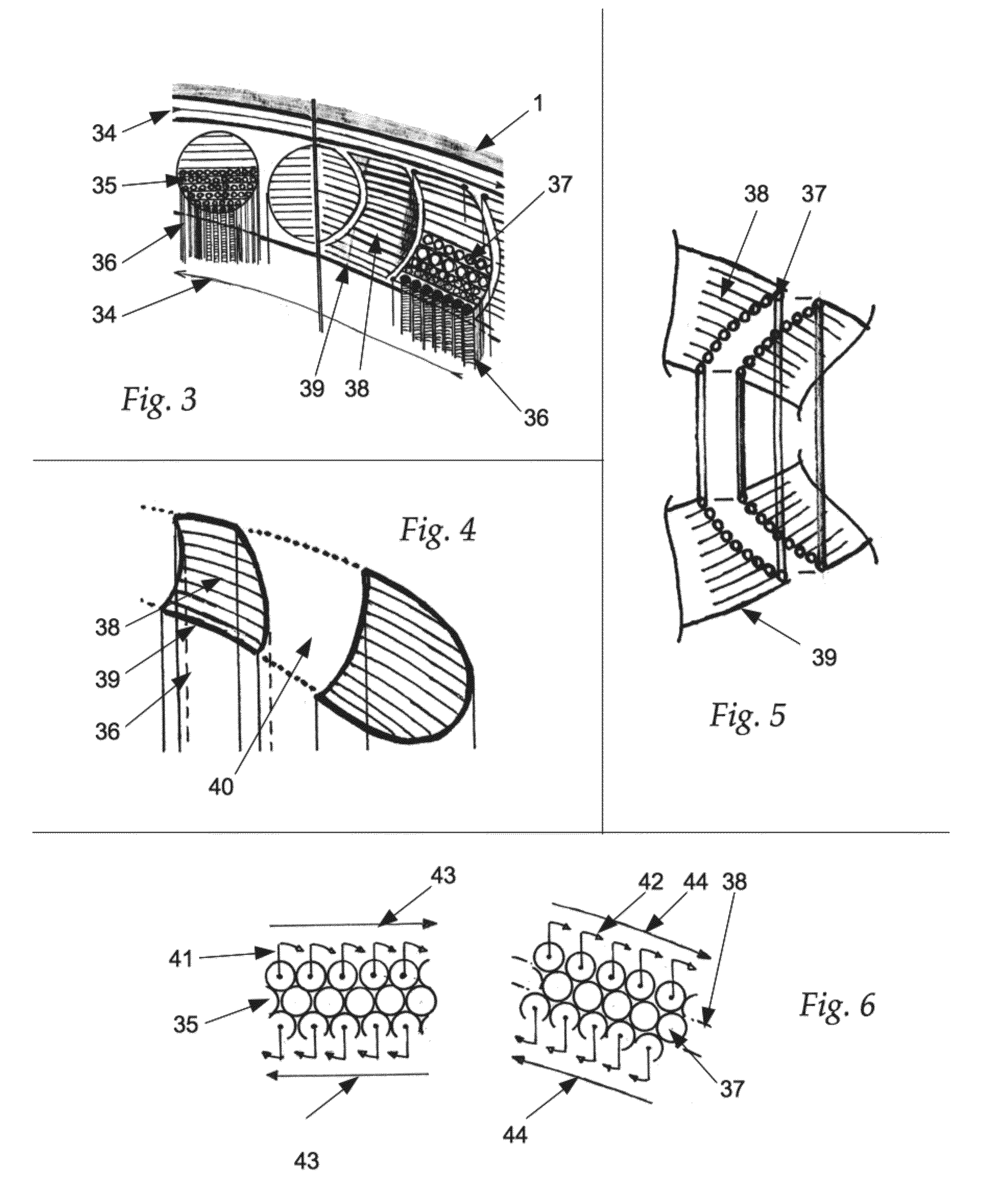
[0020]FIG. 3 is a diagram illustrating main coil electromagnetic components of the apparatus of FIGS. 1 and 2 in greater detail.

[0021]FIG. 4 is a diagram illustrating a cross section of two coil segments separated by another coil segment (not shown; implied by the intervening space) that can be used in the apparatus of FIGS. 1 and 2.

[0022]FIG. 5 is a diagram illustrating the fitting betwe...


PUM


Abstract

A magnetic field generating apparatus comprises two or more co-facing, coaxial magnetic field generators configured to generate equivalent magnetic fields directed toward a symmetrically central convergence plane; a magnetically shielding encasement configured to contain all of the associated magnetic fields generated by the coaxial magnetic field generators; and articulation frames and supports for positioning of the apparatus about a fixed point, wherein the generated magnetic fields are counter-rotated relative to one another.

Description

RELATED APPLICATIONS INFORMATION[0001]This application claims priority under 35 U.S.C. §119(e) to U.S. Provisional Patent Application No. 62 / 064,372, filed Oct. 15, 2014, and titled Magnetic Field Structures, Filed Generators, Navigation and Imaging for Untethered Robotic Device Enabled Medical Procedures which is incorporated herein by reference in its entirety as if set forth in full.BACKGROUND[0002]1. Technical Field[0003]The embodiments described herein are related to the use of magnetic fields and imaging with respect to medical procedures, and more particularly to robotic magnetic medicine.[0004]2. Related Art[0005]A wide variety of medical procedures are currently performed with undesirable and unavoidable effects on the patient that include damage to healthy tissue during surgery and distribution of therapeutic substances (drugs, antibodies, vaccines and regenerative cells) to sites other than the intended target. Non-disease related surgery increases the risk of sepsis, sca...

Claims


Application Information

Patent Timeline
IPC IPC(8): H01F7/20A61B19/00
CPCH01F7/202A61B2019/5454A61B5/055A61B19/2203G01R33/3815G01R33/381G01R33/4215A61B34/30A61B2090/3954A61B2560/063A61B5/4836H01F6/06A61B5/0036
Inventor SUZARA, VINCENT
Owner SUZARA VINCENT
Learn More