Glass panel and method for manufacturing the same

a glass panel and liquid crystal display technology, applied in the field of glass panel manufacturing, can solve the problems of high cost, high cost, and inability to save materials and steps, and achieve the effect of high cost, inability to save materials and steps, and easy errors

Inactive Publication Date: 2016-04-21
SHENZHEN CHINA STAR OPTOELECTRONICS TECH CO LTD
View PDF5 Cites 3 Cited by
  • Summary
  • Abstract
  • Description
  • Claims
  • Application Information

AI Technical Summary

Benefits of technology

[0011]In the prior art, a unique variety of masks is necessary for each type of low color shift design structure, such as an n+1 type low color shift design and an n+2 type low color shift design, for the performances of procedure steps including exposure, etching, etc. As can be seen, the manufacturing proced

Problems solved by technology

As can be seen, the manufacturing procedure thereof is rather tedious.
Moreover, when one manufacturing type is switched to another, all masks should be replaced by new ones, which results in high costs and is against saving materials and steps.
In addition, where different masks are inappropri

Method used


Image

  • Glass panel and method for manufacturing the same
  • Glass panel and method for manufacturing the same
  • Glass panel and method for manufacturing the same

Examples


Embodiment Construction

[0040]In the following, the present disclosure will be further explained in connection with the accompanying drawings.

[0041]The present disclosure provides a glass panel.

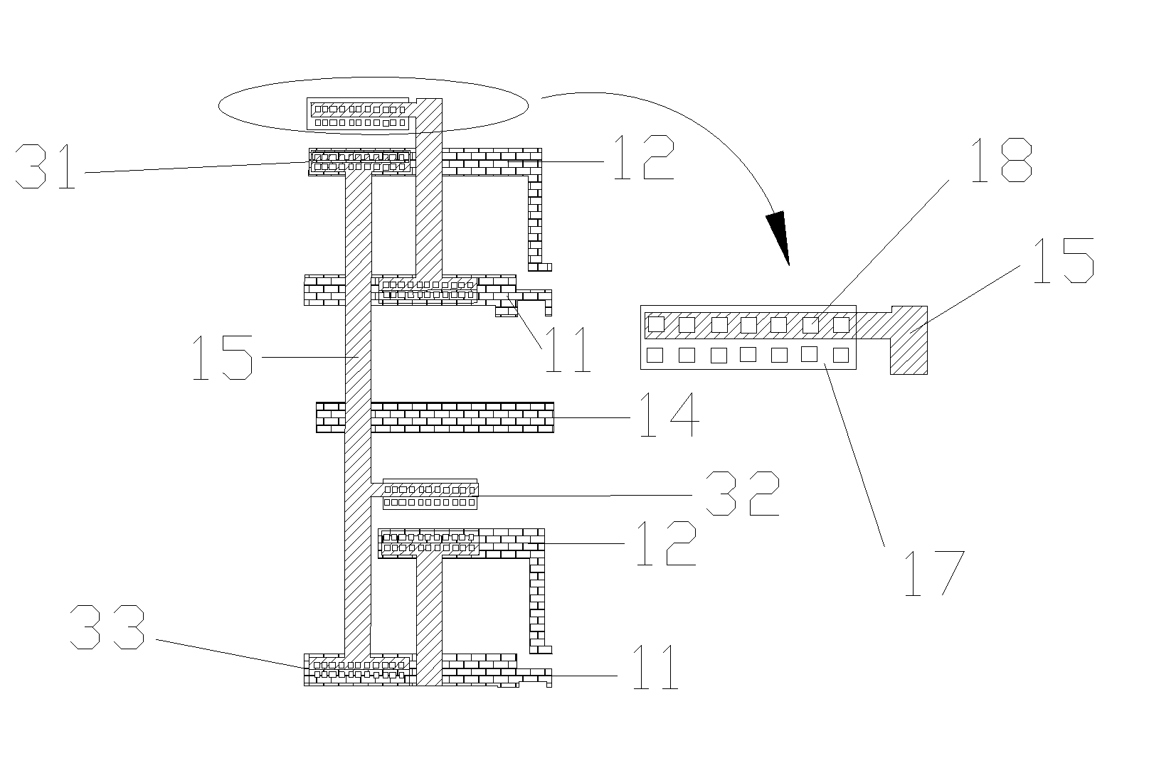
[0042]FIG. 6 schematically shows the structure of a glass panel with an n+2 type low color shift structure according to the present disclosure. As shown in FIG. 6, the glass panel according to the present disclosure comprises a first metal layer M1 used for forming scan lines 11 and charge sharing lines 12. One scan line 11 and one relevant charge sharing line 12 jointly correspond to a line of pixel units on the glass panel.

[0043]In a five mask procedure, the first metal layer M1 is formed through a first mask. That is, positions of the scan lines 11 and the charge sharing lines 12 are determined by a pattern of the first mask. The metal layer M1 can further comprise a common line 14 therein.

[0044]The glass panel according to the present disclosure further comprises a wiring metal layer used for forming connecting ...


PUM


Abstract

The field of manufacturing liquid crystal display panels, and in particular a modified glass panel is related. The glass panel comprises: a first metal layer used for forming scan lines and charge sharing lines, and a wiring metal layer used for forming connecting wires, wherein the connecting wires each have a via hole portion, and connect to the scan line and/or the charge sharing line via a via hole in the via hole portion. A corresponding manufacturing method is further provided. In this manner, a subsequently activated scan line can be used for activating a charge sharing line in a previous group. Hence, a reduced amount of chips on film will be used in the manufacturing and packaging procedures.

Description

CROSS-REFERENCE TO RELATED APPLICATIONS[0001]The present application claims benefit of Chinese patent application CN 201410559637.4, entitled “Glass panel and mask used in manufacturing the same” and filed on Oct. 20, 2014, the entirety of which is incorporated herein by reference.FIELD OF THE DISCLOSURE[0002]The present disclosure relates to the field of manufacturing liquid crystal display panels, and in particular, to a glass panel and a method for manufacturing the glass panel.BACKGROUND OF THE DISCLOSURE[0003]In the prior art, procedure steps as depicted in FIG. 1 are generally used for manufacturing an array substrate of a thin film transistor liquid crystal display. As indicated in FIG. 1, the procedure steps comprise: step a) coating a film on a glass substrate; step b) coating a photoresist material on the film; step c) illuminating the glass panel coated with the photoresist material through a mask 105; step d) developing images; step e) etching the glass panel; and step f...

Claims


Application Information

Patent Timeline
IPC IPC(8): H01L27/12G02F1/1368
CPCH01L27/124H01L27/1288G02F1/1368
Inventor HUAN, SHISHUAI
Owner SHENZHEN CHINA STAR OPTOELECTRONICS TECH CO LTD
Why Eureka
Try Eureka