
Robotic Swarm Localization Using Ranging Radios

a robotic swarm and radio technology, applied in the field of autonomous control of small robotic platforms, can solve the problems of small payload and usually low cost, limiting the accuracy of the robot swarm, brittle in some environments, and inability to carry accurate robot swarms, etc., to achieve the effect of extending the localization workspace and high accuracy

Active Publication Date: 2016-04-28
ROBOTIC RES OPCO LLC
View PDF3 Cites 13 Cited by
  • Summary
  • Abstract
  • Description
  • Claims
  • Application Information

AI Technical Summary

Benefits of technology

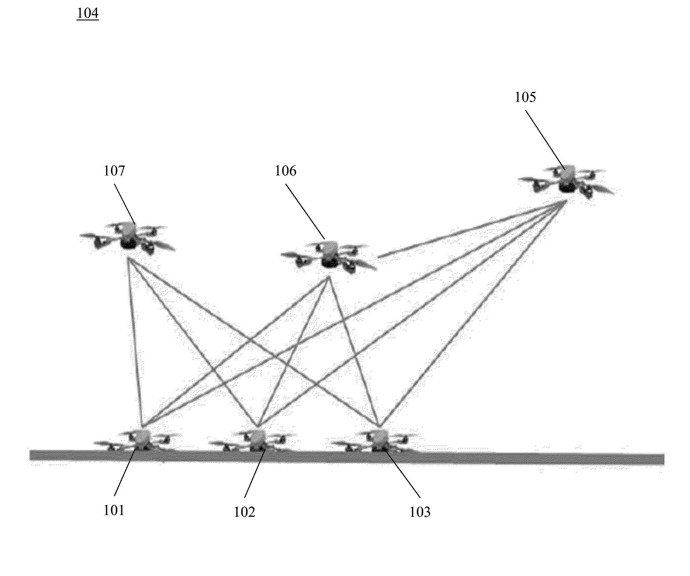
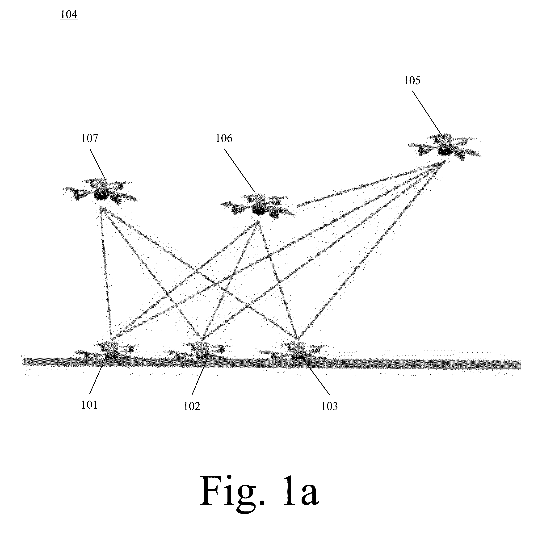
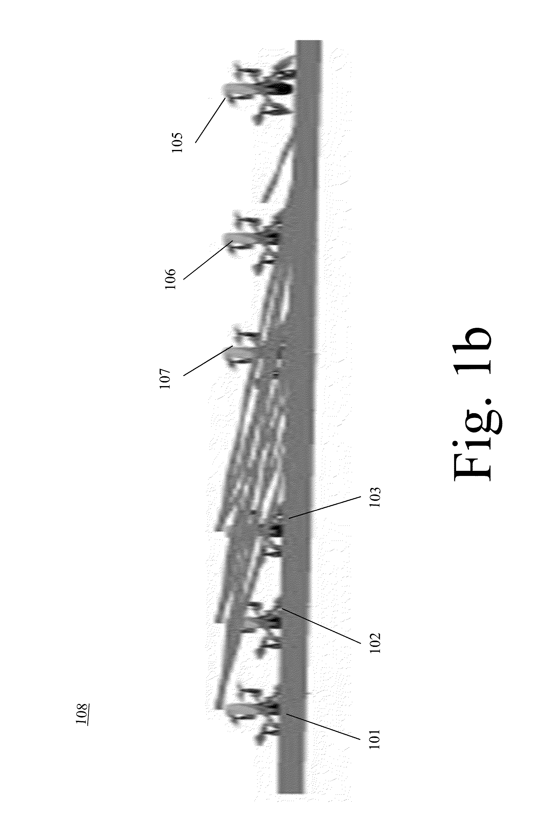
The invention is a way to keep track of moving platforms using stationary platforms, moving platforms, and ranging radios. The stationary platforms give information for the moving platforms to keep them in the correct place. Increasing the number of stationary platforms can improve accuracy, and moving them around can change the workspace where the localization is done. This system helps make sure everything is in the correct place.

Problems solved by technology

There are several challenges related to the autonomous control of small robotic platforms.
The small payload and usually low cost restrict them from carrying accurate, inertial localization systems.
Therefore, in GPS denied areas, automatic tasks—like mapping and searching—become a challenge.
The problem with these techniques is that they are brittle in some environments; in particular, tunnels, caves, and man-made structures pose some challenges.
Poor lighting conditions, low quality cameras, and dusty or smoky conditions further exacerbate the localization errors.
For example, state-of-the-art quadrotors equipped with quality cameras, flying in a sufficiently-lit tunnel, while using visual odometry, may achieve 5% to 10% error as a function of distance travelled.
If the tunnel is dusty or smoky, the error in localization is driven by the inertial components.
Therefore, small bias errors in acceleration become exponential errors in position.
If the visual or LADAR odometry is blocked by smoke or dust, and no longer seeing features, the position error will grow exponentially.
This is due to the double integration errors, and the lack of other sensors contributing to the bias estimates.
The problems with localization become very evident on flying platforms, as they do not have wheel odometry to maintain the inertial biases.
In small robotic platforms where the wheel slippage is large, the localization estimates also suffer accordingly.

Method used


Image

  • Robotic Swarm Localization Using Ranging Radios
  • Robotic Swarm Localization Using Ranging Radios
  • Robotic Swarm Localization Using Ranging Radios

Examples


Embodiment Construction

[0014]In the following detailed description of the invention of exemplary embodiments of the invention, reference is made to the accompanying drawings (where like numbers represent like elements), which form a part hereof, and in which is shown by way of illustration specific exemplary embodiments in which the invention may be practiced. These embodiments are described in sufficient detail to enable those skilled in the art to practice the invention, but other embodiments may be utilized and logical, mechanical, electrical, and other changes may be made without departing from the scope of the present invention. The following detailed description is, therefore, not to be taken in a limiting sense, and the scope of the present invention is defined only by the appended claims.

[0015]In the following description, numerous specific details are set forth to provide a thorough understanding of the invention. However, it is understood that the invention may be practiced without these specifi...


PUM


Abstract

A system for localizing a swarm of robotic platforms utilizing ranging sensors. The swarm is localized by purposely leaving some of the platforms of the swarm stationary, providing localization to the moving ones. The platforms in the swarm can alternate between a stationary and moving state.

Description

CROSS REFERENCE TO RELATED APPLICATIONS[0001]This application claims priority from U.S. Patent Application Ser. No. 62 / 059,124, entitled “Robotic Swarm Localization Using Ranging Radios”, filed on 2 Oct. 2014. The benefit under 35 USC §119(e) of the United States provisional application is hereby claimed, and the aforementioned application is hereby incorporated herein by reference.FEDERALLY SPONSORED RESEARCH[0002]Not ApplicableSEQUENCE LISTING OR PROGRAM[0003]Not ApplicableTECHNICAL FIELD OF THE INVENTION[0004]The present invention relates generally to the autonomous control of small robotic platforms. More specifically, the present invention relates to robotic localization.BACKGROUND OF THE INVENTION[0005]There are several challenges related to the autonomous control of small robotic platforms. The small payload and usually low cost restrict them from carrying accurate, inertial localization systems. Therefore, in GPS denied areas, automatic tasks—like mapping and searching—becom...

Claims


Application Information

Patent Timeline
Patent Type & Authority Applications(United States)
IPC IPC(8): B25J9/16B25J5/00G01S17/933
CPCB25J9/1694B25J9/1669Y10S901/01B25J5/00B25J9/1666G05D1/104B25J9/1617G01S17/08G01S17/933G05B2219/39146B64U2201/102G01S5/0289
Inventor LACAZE, ALBERTO DANIELMURPHY, KARL NICHOLASPUTNEY, JOSEPHSCHNEIDER, ANNE RACHEL
Owner ROBOTIC RES OPCO LLC
Learn More