Semiconductor device
a technology of semiconductor devices and capacitors, applied in the direction of semiconductor devices, basic electric elements, electrical equipment, etc., to achieve the effect of increasing the feedback capacitance, increasing the capacitance “crss”, and reducing the capacitance between the gate potential
- Summary
- Abstract
- Description
- Claims
- Application Information
AI Technical Summary
Benefits of technology
Problems solved by technology
Method used
Image
Examples
first embodiment
Configuration
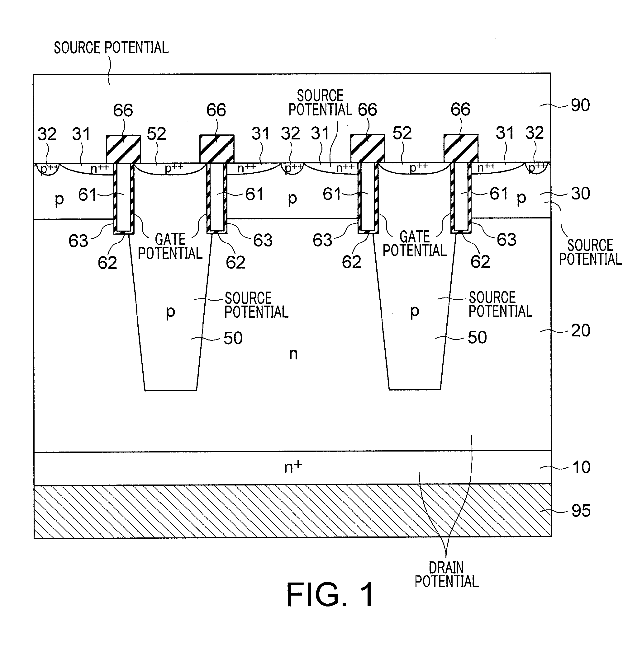
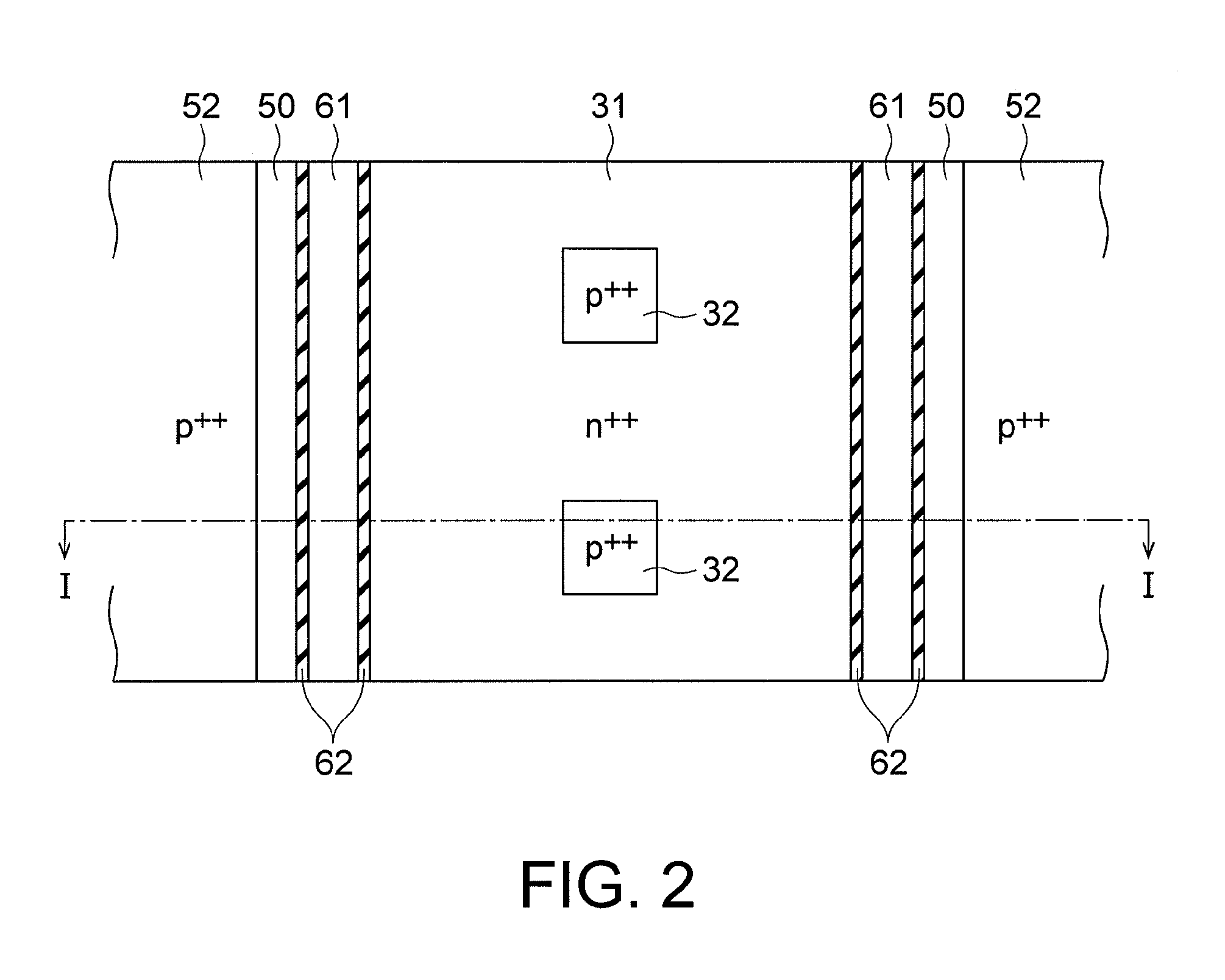
[0043]In the following, a semiconductor device according to a first embodiment of the present invention will be described with reference to the drawings. FIGS. 1 to 3 are diagrams for illustrating the first embodiment of the present invention.
[0044]A semiconductor device according to this embodiment is a vertical power MOSFET, for example. In the following, the semiconductor device will be described as a vertical power MOSFET. However, note that the vertical power MOSFET is only an example of the semiconductor device.
[0045]As shown in FIG. 1, the semiconductor device according to this embodiment includes an n-type semiconductor substrate 10 of high impurity concentration (the “n-type” corresponds to a “first conductivity type” in the claims), a n-type drift layer 20 of low impurity concentration formed on the n-type semiconductor substrate of high impurity concentration, a p-type base layer 30 disposed on the drift layer 20 (the “p-type” corresponds to a “second conduct...
second embodiment
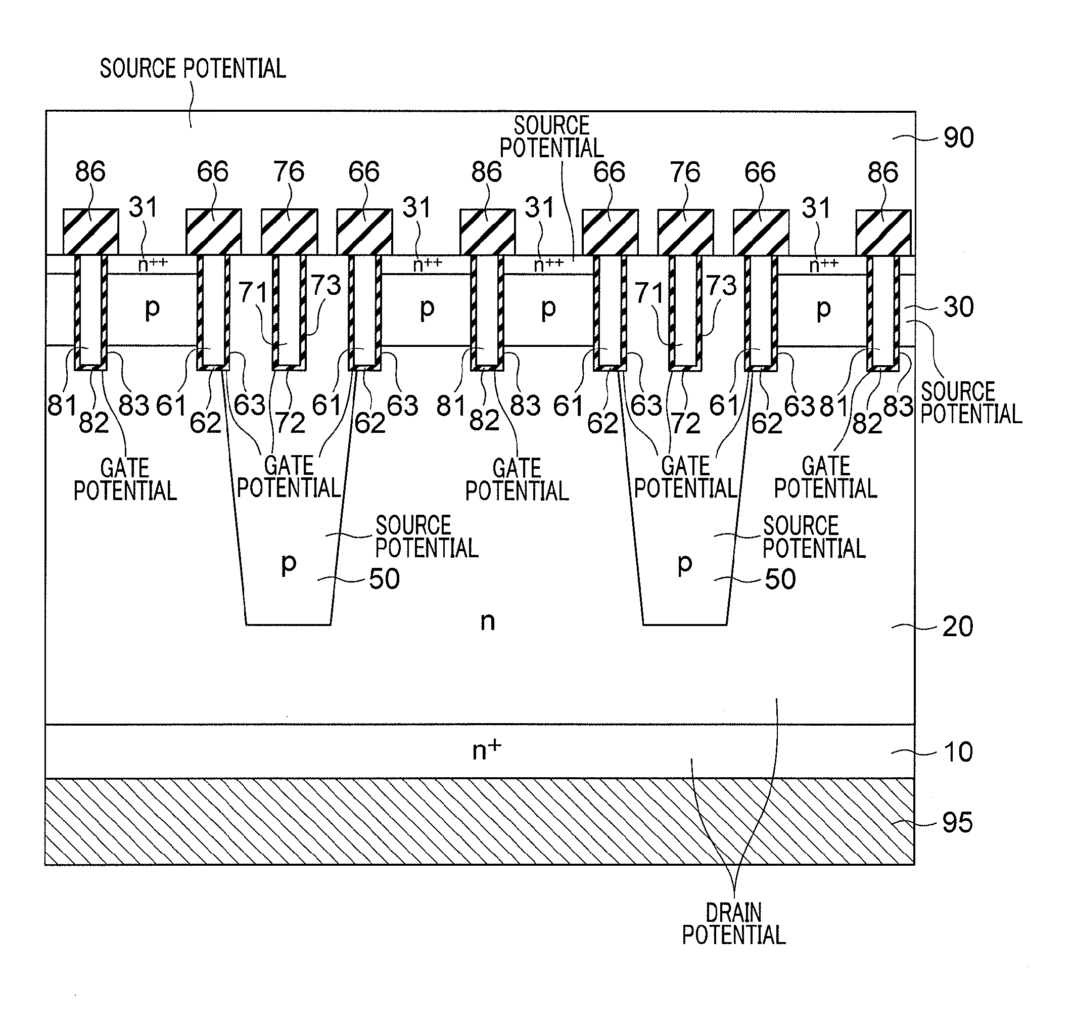
[0073]Next, a second embodiment of the present invention will be described mainly with reference to FIGS. 4, 5 and 11.
[0074]According to the second embodiment, in addition to the first gate electrode 61 and the first insulating layer 62 according to the first embodiment, a second gate electrode 71 surrounded by a second insulating layer 72 is provided in the column layer at an intermediate position in the horizontal direction between the pair of first gate electrodes 61. The second insulating layer 72 and the second gate electrode 71 are disposed in a second trench 73 formed in the column layer 50. The second gate electrode 71 is also at the gate potential.
[0075]In addition, according to this embodiment, a second interlayer insulating film 76 is formed on an upper surface of the second gate electrode 71 and the second insulating layer 72. Viewed from above, the second gate electrode 71, the second insulating layer 72 and the second interlayer insulating film 76 are shaped in a strip...
third embodiment
[0084]Next, a third embodiment of the present invention will be described mainly with reference to FIGS. 6 to 8.
[0085]According to the third embodiment, in addition to the first gate electrode 61 and the first insulating layer 62 according to the first embodiment, a third gate electrode 81 surrounded by a third insulating layer 82 is provided between two adjacent column layers 50. The third insulating layer 82 and the third gate electrode 81 are disposed in a third trench 83 that extends from the source region 31 into the drift layer 20. The third gate electrode 81 is also at the gate potential.
[0086]In addition, according to this embodiment, a third interlayer insulating film 86 is formed on an upper surface of the third gate electrode 81 and the third insulating layer 82. Viewed from above, the third gate electrode 81, the third insulating layer 82 and the third interlayer insulating film 86 are shaped in a striped pattern (see FIG. 7 for the third gate electrode 81 and the third ...
PUM
 Abstract
Description
Claims
Application Information
 - R&D
- Intellectual Property
- Life Sciences
- Materials
- Tech Scout
- Unparalleled Data Quality
- Higher Quality Content
- 60% Fewer Hallucinations
Browse by: Latest US Patents, China's latest patents, Technical Efficacy Thesaurus, Application Domain, Technology Topic, Popular Technical Reports.
© 2025 PatSnap. All rights reserved.Legal|Privacy policy|Modern Slavery Act Transparency Statement|Sitemap|About US| Contact US: help@patsnap.com


