
Methods for operating wind turbine system having dynamic brake

a technology of wind turbines and brakes, applied in the direction of dynamo-electric converter control, electric generator control, machines/engines, etc., can solve the problems of wind turbine power generation and power receipt, excessive energy, and damage to converters, so as to reduce the power generation of wind turbines

Active Publication Date: 2016-04-28
GENERAL ELECTRIC CO
View PDF8 Cites 26 Cited by
  • Summary
  • Abstract
  • Description
  • Claims
  • Application Information

AI Technical Summary

Benefits of technology

The patent is about a method for operating a wind turbine system that can effectively respond to grid faults. The system includes a controller that can detect when the dynamic brake of the power converter is gated on. It can then decide if there is a grid fault or not. If there is no fault, the system reduces power generation to avoid overloading the grid. If there is a fault, the system blocks the power converter to prevent damage to the grid. This helps to ensure the safe and efficient operation of wind turbines in such conditions.

Problems solved by technology

During operation of wind turbine systems, including DFIG systems, various grid faults can occur, which result in a disconnect between generation of power by the wind turbine and receipt of that power by the grid.
This can result in excessive energy in the power converter, which can cause damage to the converter.
However, conventional dynamic brake systems are not without drawbacks.
For example, when a dynamic brake is gated on, the line side of the power converter is not protected from excess energy.
This excess line side energy can be transmitted through, and damage, the line side of the converter.
Further, in some cases during operation of dynamic brakes, a dynamic brake may be gated off due to increased temperature conditions before sufficient energy has been absorbed, thus again risking damage to the power converter.

Method used


Image

  • Methods for operating wind turbine system having dynamic brake
  • Methods for operating wind turbine system having dynamic brake
  • Methods for operating wind turbine system having dynamic brake

Examples


Embodiment Construction

[0021]Reference now will be made in detail to embodiments of the invention, one or more examples of which are illustrated in the drawings. Each example is provided by way of explanation of the invention, not limitation of the invention. In fact, it will be apparent to those skilled in the art that various modifications and variations can be made in the present invention without departing from the scope or spirit of the invention. For instance, features illustrated or described as part of one embodiment can be used with another embodiment to yield a still further embodiment. Thus, it is intended that the present invention covers such modifications and variations as come within the scope of the appended claims and their equivalents.

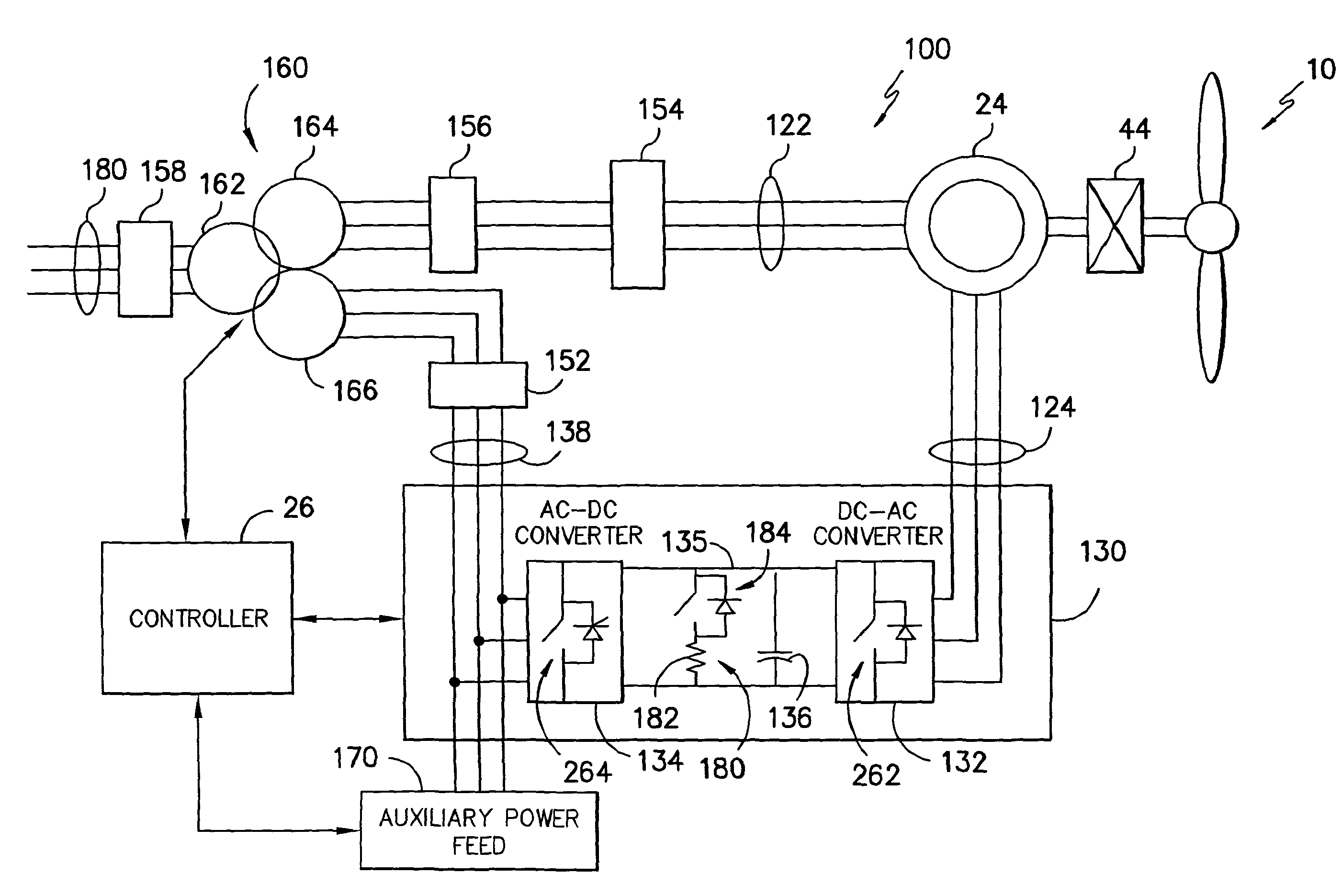
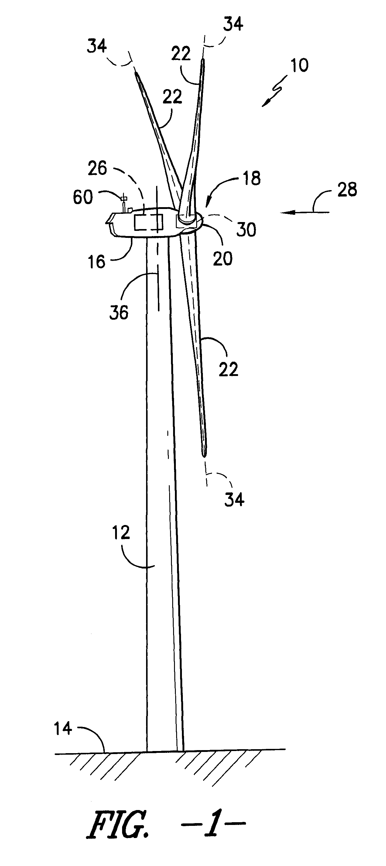
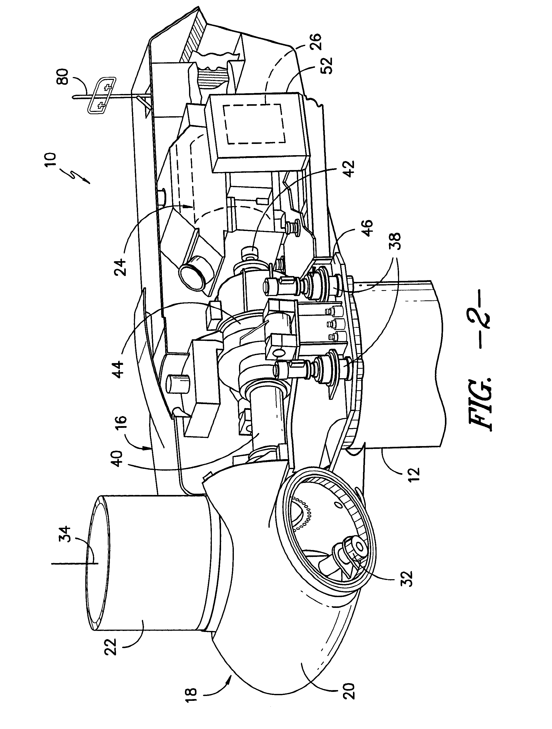
[0022]FIG. 1 illustrates a perspective view of one embodiment of a wind turbine 10. As shown, the wind turbine 10 includes a tower 12 extending from a support surface 14, a nacelle 16 mounted on the tower 12, and a rotor 18 coupled to the nacelle 16. The ro...


PUM


Abstract

Methods for operating a wind turbine system are provided. In one embodiment, a method includes adjusting a threshold direct current (DC) bus voltage for a dynamic brake in a wind turbine power converter above a reference DC bus voltage based on at least one system condition. The method further includes gating the dynamic brake on when an experienced DC bus voltage is equal to or greater than the threshold DC bus voltage, and inputting a dynamic brake condition into a controller when the dynamic brake is gated on. The method further includes determining if a grid fault has occurred, reducing power generation of the wind turbine if no grid fault has occurred, and blocking the power converter if a grid fault has occurred. The method further includes gating the dynamic brake off when the experienced DC bus voltage is less than the threshold DC bus voltage.

Description

FIELD OF THE INVENTION[0001]The present disclosure relates generally to wind turbines, and more particularly to methods for operating such wind turbines and in particular dynamic braking of such systems.BACKGROUND OF THE INVENTION[0002]Wind turbines have received increased attention as a renewable energy source. Wind turbines use the wind to generate electricity. The wind turns multiple blades connected to a rotor. The spin of the blades caused by the wind spins a shaft of the rotor, which connects to a generator that generates electricity. Certain wind turbines include a doubly fed induction generator (DFIG) to convert wind energy into electrical power suitable for output to an electrical grid. DFIGs are typically connected to a converter that regulates the flow of electrical power between the DFIG and the grid. More particularly, the converter allows the wind turbine to output electrical power at the grid frequency regardless of the rotational speed of the wind turbine blades.[000...

Claims


Application Information

Patent Timeline
Patent Type & Authority Applications(United States)
IPC IPC(8): H02H7/06H02P9/00F03D7/04F03D9/00F03D1/06F03D7/02
CPCH02H7/067F03D1/0675F03D7/0244F03D7/0224F03D9/005F03D7/0284F03D9/003H02P9/007F03D7/042F03D7/0272H02P9/10F05B2260/903F03D9/255F03D9/257H02J2300/28H02J3/381Y02E10/72Y02E10/76
Inventor ZHU, HUIBINWU, XUEQINCHANG, SHOUZHONGDING, JIE
Owner GENERAL ELECTRIC CO
Learn More