

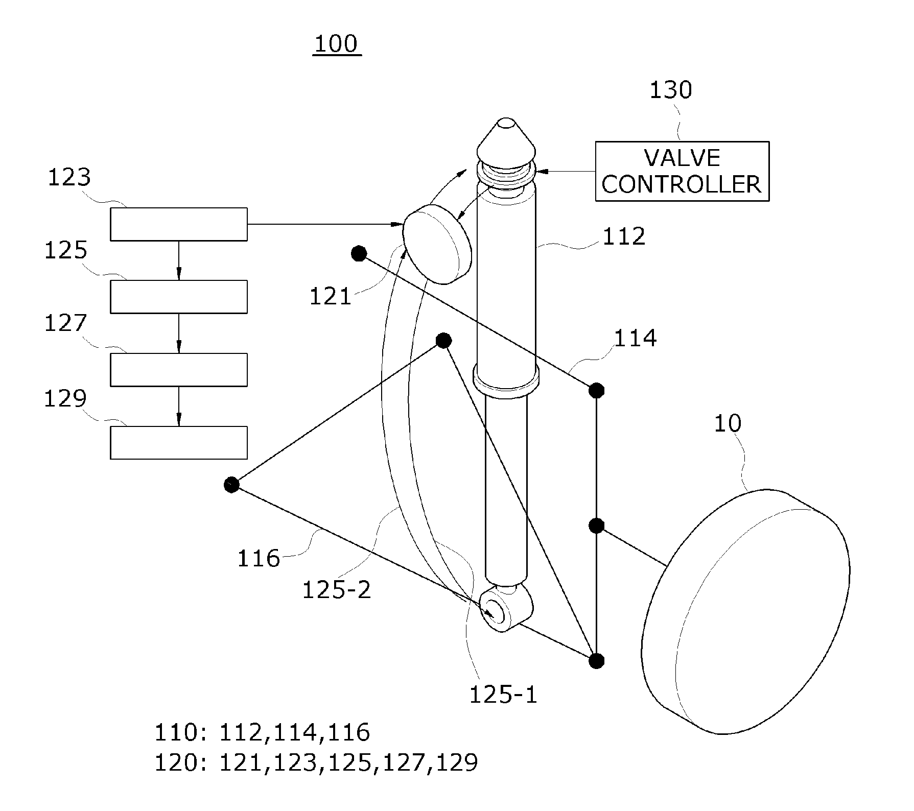
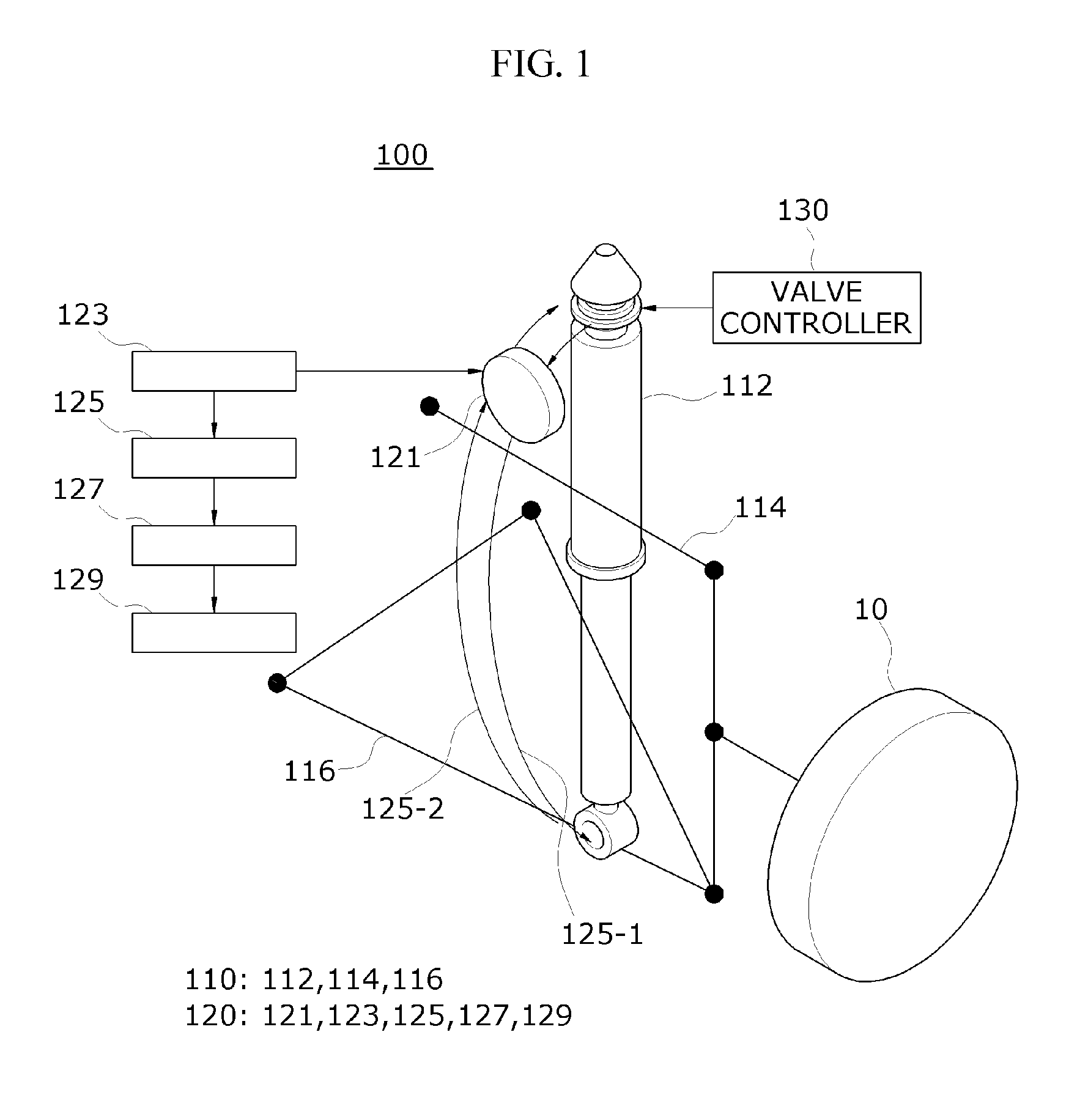
Electric power generating apparatus using suspension device
a technology of electric power generation apparatus and suspension device, which is applied in the direction of mechanical apparatus, shock absorbers, transportation and packaging, etc., can solve the problems of obstructing the shock absorbing operation of energy recovery apparatus, affecting the ride quality, and affecting the smooth absorbing of shock, so as to prevent the deformation of the damping performance of the suspension devi
- Summary
- Abstract
- Description
- Claims
- Application Information
AI Technical Summary
Benefits of technology
Problems solved by technology
Method used
Image

Examples
first embodiment
[0053]FIGS. 3A and 3B are diagrams illustrating a cross-sectional structure of an upper discharge valve 112A according to a first embodiment of the present invention and an internal configuration of the valve controller 130 illustrated in FIG. 1. FIG. 3A illustrates a state where the upper discharge valve 112A is closed, and FIG. 3B illustrates a state where the upper discharge valve 112A is opened.
[0054]Referring to FIGS. 3A and 3B, the upper discharge valve 112A according to the first embodiment of the present invention may disconnect the damper 112 from the turbine unit 121 according to an opening / closing control method using an electromagnet.
[0055]In detail, the upper discharge valve 112A according to the first embodiment of the present invention may include a body 112A-9 including a nozzle 112A-10 disposed on one end of the body 112A-9, a needle 112A-1 that moves inside the body 112A-9, a spring member 112A-7 that pushes the needle 112A-1 in a direction toward the nozzle 112A-1...
second embodiment
[0071]FIGS. 4A and 4B are diagrams illustrating a cross-sectional structure of an upper discharge valve 112A according to a second embodiment of the present invention and an internal configuration of the valve controller 130 illustrated in FIG. 1. FIG. 4A illustrates a state where the upper discharge valve 112A is closed, and FIG. 4B illustrates a state where the upper discharge valve 112A is opened.
[0072]Referring to FIGS. 4A and 4B, the upper discharge valve 112A according to the second embodiment of the present invention may have a difference with the first embodiment in that the upper discharge valve 112A according to the second embodiment is configured to disconnect the damper 112 from the turbine unit 121 according to an opening / closing control method using a screw-nut pair.
[0073]In detail, the upper discharge valve 112A according to the second embodiment may include a body 112A-9 including a nozzle 112A-10 disposed at one end of the body 112A-9, a needle 112A-1 that rectiline...
PUM
 Abstract
Description
Claims
Application Information