Air blowing device

a technology of air blowing device and air outlet, which is applied in the direction of ducting arrangement, lighting and heating apparatus, heating types, etc., can solve the problems of difficult to keep the air outlet visible, the function of the related-art device to adjust the flow direction of the blowing airflow may be impaired, and the air outlet may be difficult to see. , to achieve the effect of facilitating the downsizing and manufacturing reducing the manufacturing cost of the air blowing devi

Inactive Publication Date: 2016-05-05
HOWA PLASTICS CO LTD
View PDF2 Cites 5 Cited by
  • Summary
  • Abstract
  • Description
  • Claims
  • Application Information

AI Technical Summary

Benefits of technology

[0024]For example, when employing a valve body capable of varying the passage area of the airflow passage as the flow velocity adjusting mechanism, the flow velocity of the airflow passing through the air outlet can be adjusted with relatively simple structure. As a result, the downsizing and manufacture of the air blowing device can be facilitated, and hence the manufacturing cost of the air blowing device can be reduced.
[0025]In view of the above, in the air blowing device according to the aspect of the present invention, the flow velocity adjusting mechanism may be a valve body capable of varying a passage area of the airflow passage, and the valve body may increase the flow velocity by reducing the passage area, and may reduce the flow velocity by increasing the passage area.

Problems solved by technology

However, when the mask is inadvertently arranged in the vicinity of the air outlet of the related-art device, the flow direction of the blowing airflow may be changed to an unintended direction due to the mask though the air outlet may be kept invisible.
That is, when the air outlet is kept invisible, the function of the related-art device to adjust the flow direction of the blowing airflow may be impaired.
As described above, it is not easy to keep the air outlet invisible while maintaining the function as the air blowing device.

Method used


Image

  • Air blowing device
  • Air blowing device
  • Air blowing device

Examples


Embodiment Construction

[0031]Now, an air blowing device according to embodiments of the present invention is described referring to the drawings.

[0032]

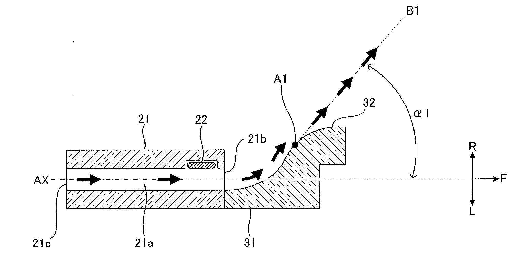
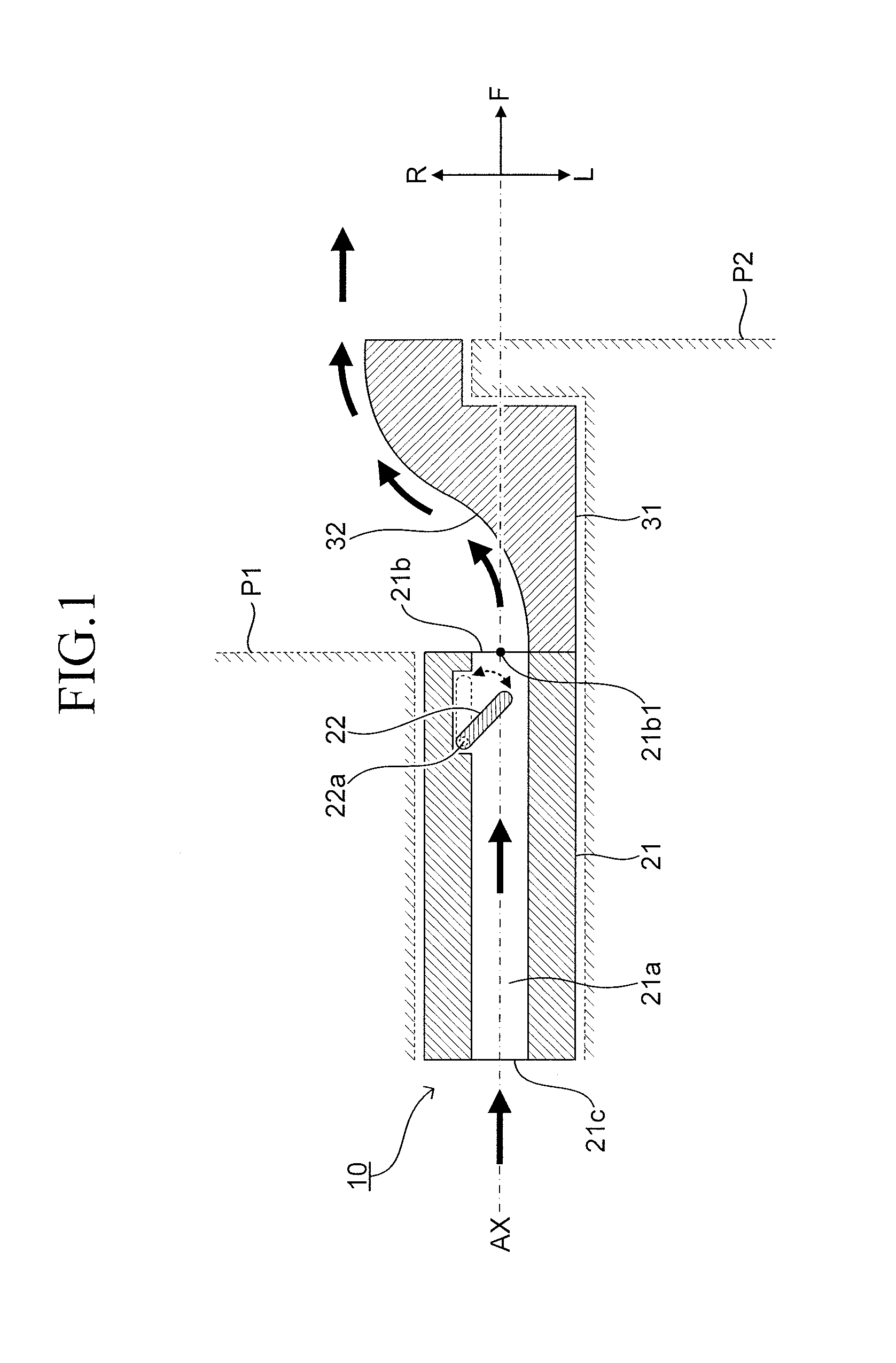
[0033]FIG. 1 is an illustration of a schematic configuration of an air blowing device 10 according to an embodiment of the present invention (hereinafter referred to as “embodiment device 10”). The embodiment device 10 is installed on an instrument panel of an automobile so as to be interposed between a peripheral component P1 and a peripheral component P2. Note that, in this embodiment, the peripheral component P1 is a housing of the instrument panel, and the peripheral component P2 is an exterior portion of a display of a car navigation system.

[0034]Specifically, the embodiment device 10 includes a hollow columnar portion for allowing an airflow to pass therethrough (tubular body 21 described later), and a shelf-like portion, i.e. a rising portion like a continental slope adjacent to a continental shelf, for allowing the airflow to be guided along a curve...


PUM


Abstract

Provided is an air blowing device capable of keeping an air outlet invisible to the extent possible without impairing a function as the air blowing device. An air blowing device (10) includes: a tubular body (21) defining an airflow passage (21a) and an air outlet (21b); a guide wall (31) for guiding an airflow having passed through the air outlet in an intended direction; and a flow velocity adjusting mechanism (valve body) (22) capable of adjusting a flow velocity of the airflow passing through the air outlet. The guide wall has a convex surface shape protruding in a direction intersecting with a forward direction of the air outlet, and is arranged so that a projection image, which is obtained by projecting the guide wall onto an imaginary plane including the air outlet, covers the entire air outlet. The flow velocity adjusting mechanism is configured to adjust the flow velocity in accordance with the intended direction.

Description

BACKGROUND OF THE INVENTION[0001]1. Field of the Invention[0002]The present invention relates to an air blowing device including a tubular body defining an airflow passage and an air outlet, a guide wall for guiding an airflow having passed through the air outlet in an intended direction, and a flow velocity adjusting mechanism capable of adjusting a flow velocity of the airflow passing through the air outlet.[0003]2. Description of the Related Art[0004]Hitherto, there has been proposed an air blowing device for supplying cooling or heating air to a vehicle cabin of an automobile or the like. In general, this type of air blowing device is capable of adjusting a flow direction of an airflow or the like blown from the air blowing device (hereinafter referred to as “blowing airflow”).[0005]One of the related-art air blowing devices (hereinafter referred to as “related-art device”) includes a housing defining an airflow passage and an air outlet, and an upstream-side fin and a downstrea...

Claims


Application Information

Patent Timeline
Patent Type & Authority Applications(United States)
IPC IPC(8): B60H1/34
CPCB60H1/3421B60H1/00B60H1/34F16K15/20B60H1/00564B60H1/3414F24F13/081B60H2001/00721F24F13/06
Inventor YAMAMOTO, MASAAKIKANEDA, KENTAROKAJIWARA, KAZUTOMO
Owner HOWA PLASTICS CO LTD
Why Eureka
Try Eureka