Exhaust device for combustion engine

a technology of exhaust device and combustion engine, which is applied in the direction of machines/engines, mechanical equipment, gas passages, etc., can solve the problems of complicated welding process, and achieve the effect of reducing the concentration of stress

Active Publication Date: 2016-05-05
KAWASAKI MOTORS LTD
View PDF6 Cites 2 Cited by
  • Summary
  • Abstract
  • Description
  • Claims
  • Application Information

AI Technical Summary

Benefits of technology

[0007]An object of the present invention is to provide an exhaust device, for an engine, which allows concentration of stress to be

Problems solved by technology

However, in a structure in which such a gusset is provided, the number of

Method used


Image

  • Exhaust device for combustion engine
  • Exhaust device for combustion engine
  • Exhaust device for combustion engine

Examples


Embodiment Construction

[0021]Hereinafter, a preferred embodiment of the present invention will be described with reference to the drawings. In the description herein, “left side” and “right side” represent the left side and the right side, respectively, as viewed from a rider riding a vehicle.

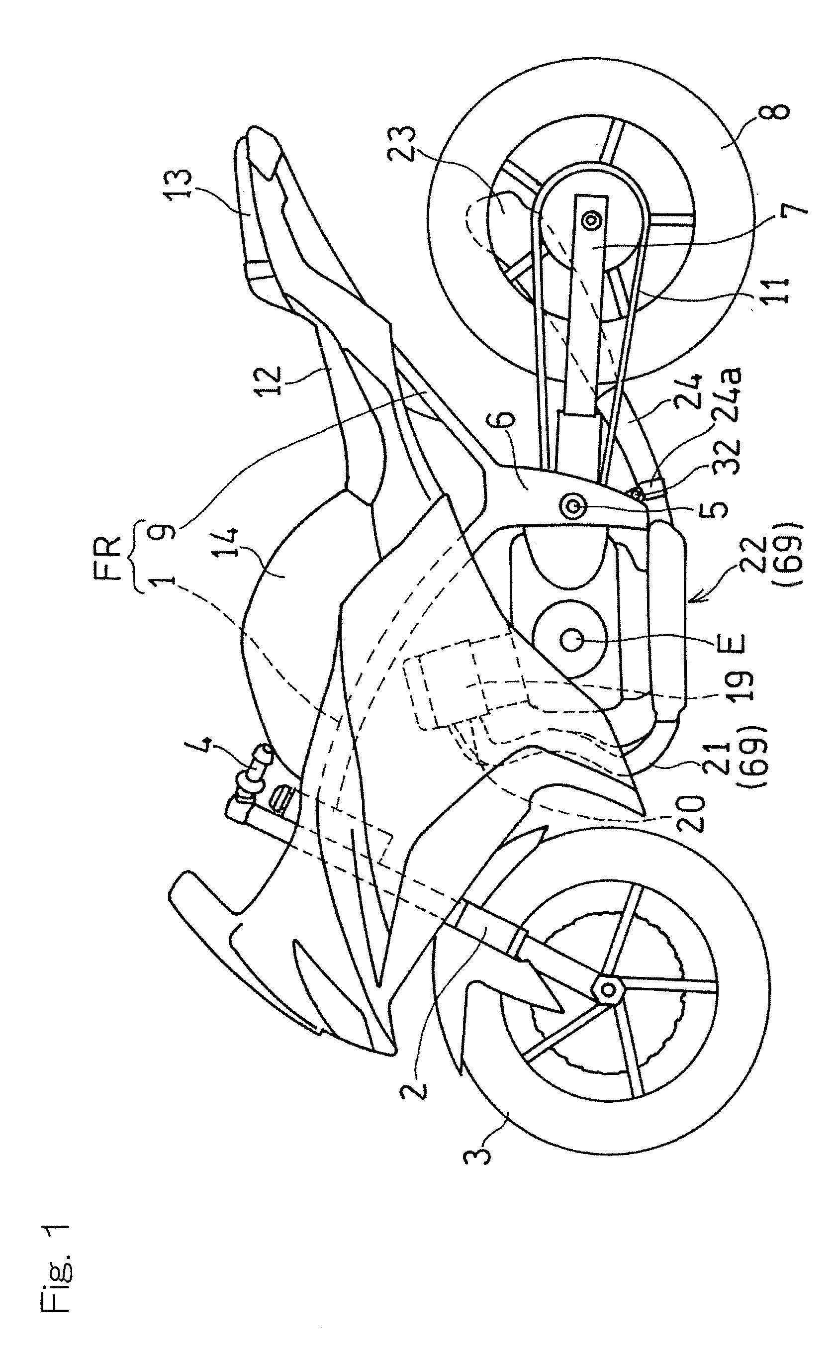
[0022]FIG. 1 is a side view of a motorcycle including an exhaust apparatus or exhaust device, for an engine, according to a preferred embodiment of the present invention. The motorcycle shown in FIG. 1 includes a vehicle body frame FR, and the vehicle body frame FR includes a main frame 1 forming a front half of the vehicle body frame FR, and a seat rail 9 which is connected to a rear portion of the main frame 1 and forms a rear half of the vehicle body frame FR. A front fork 2 is supported at the front end of the main frame 1. A front wheel 3 is mounted to the lower end of the front fork 2, and a steering handle 4 is mounted to the upper end of the front fork 2. A swing arm bracket 6 is provided at a lower portion o...


PUM


Abstract

An exhaust device for a combustion engine includes a collecting pipe to which downstream end portions of two exhaust pipes are connected. The downstream end portions of the exhaust pipes are aligned in a lateral direction perpendicular to an axial direction thereof. The downstream end portions of the exhaust pipes have insertion sections that are inserted into an upstream end portion of the collecting pipe. The upstream end portion of the collecting pipe has a cover section that covers the entirety of circumferences of the insertion sections. Outer circumferential surfaces of the insertion sections of the exhaust pipes and an inner circumferential surface of the cover section of the collecting pipe are joined over the entirety of circumferences thereof at a collecting pipe joining region. The collecting pipe joining region has a displacement portion having its position shifted in the axial direction C toward the lateral direction W.

Description

CROSS REFERENCE TO THE RELATED APPLICATION[0001]This application is based on and claims Convention priority to Japanese patent application No. 2014-220272, filed Oct. 29, 2014, the entire disclosure of which is herein incorporated by reference as a part of this application.BACKGROUND OF THE INVENTION[0002]1. Field of the Invention[0003]The present invention relates to an exhaust device that includes: a plurality of exhaust pipes for a multi-cylinder engine; and a collecting pipe connected to the downstream side portions of the exhaust pipes.[0004]2. Description of Related Art[0005]A multi-cylinder engine for a motorcycle has been known in which a plurality of exhaust pipes are collected and connected to a collecting pipe, and the collecting pipe is connected to a muffler, so that, after muffling of exhaust gas is performed by the muffler, the exhaust gas is discharged to the outside (for example, JP Laid-open Patent Publication No. H09-144535). In such an engine, the plurality of ex...

Claims


Application Information

Patent Timeline
IPC IPC(8): F01N13/10
CPCF01N13/10F01N13/1805F01N2470/16F01N2590/04
Inventor TAKANO, KIYOHITO
Owner KAWASAKI MOTORS LTD
Why Eureka
Try Eureka