
Solar and wind powered blower utilizing a flywheel and turbine

Inactive Publication Date: 2016-05-05
NIX MARTIN EUGENE
View PDF23 Cites 16 Cited by
  • Summary
  • Abstract
  • Description
  • Claims
  • Application Information

AI Technical Summary

Benefits of technology

The patent describes a system that stores energy from solar and wind sources to provide compressed air when wind energy is not available. The system includes a flywheel and turbine assembly, which stabilizes the air from a blower and ensures proper direction. Additionally, the system includes a second blower powered by wind, which further enhances the storage of energy. Overall, the system is capable of providing a consistent supply of energy for use in various applications.

Problems solved by technology

However, wind energy tends to be very available in the winter, when solar energy is not available.

Method used


Image

  • Solar and wind powered blower utilizing a flywheel and turbine
  • Solar and wind powered blower utilizing a flywheel and turbine
  • Solar and wind powered blower utilizing a flywheel and turbine

Examples


Embodiment Construction

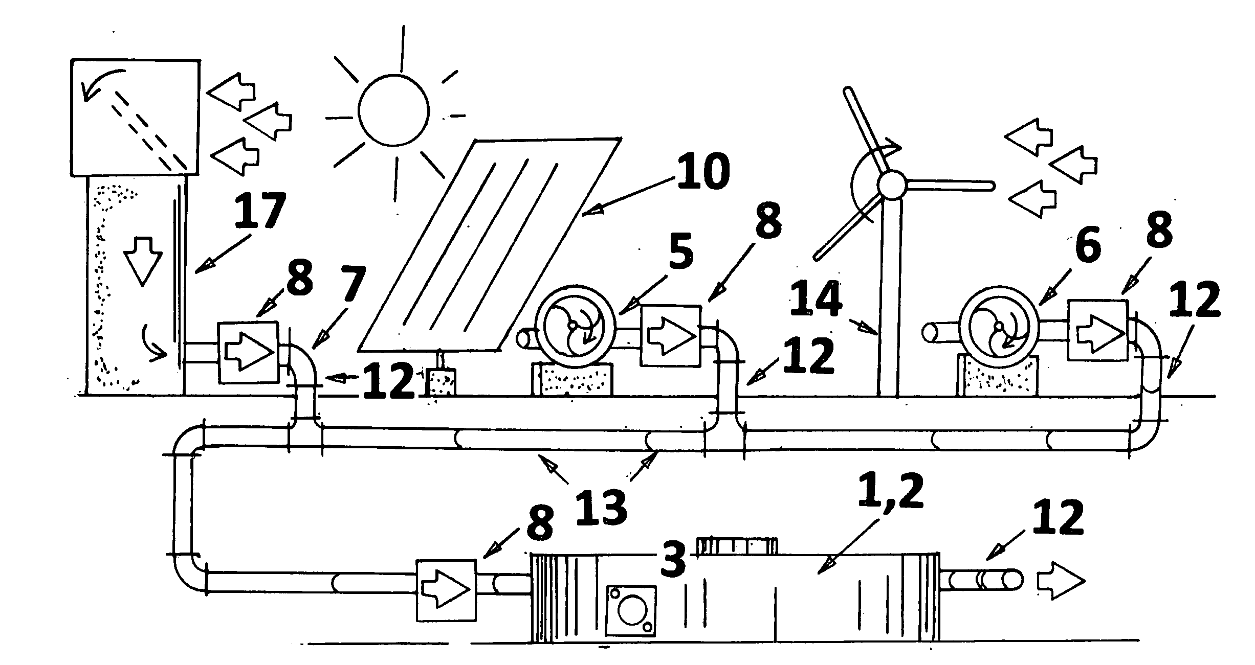
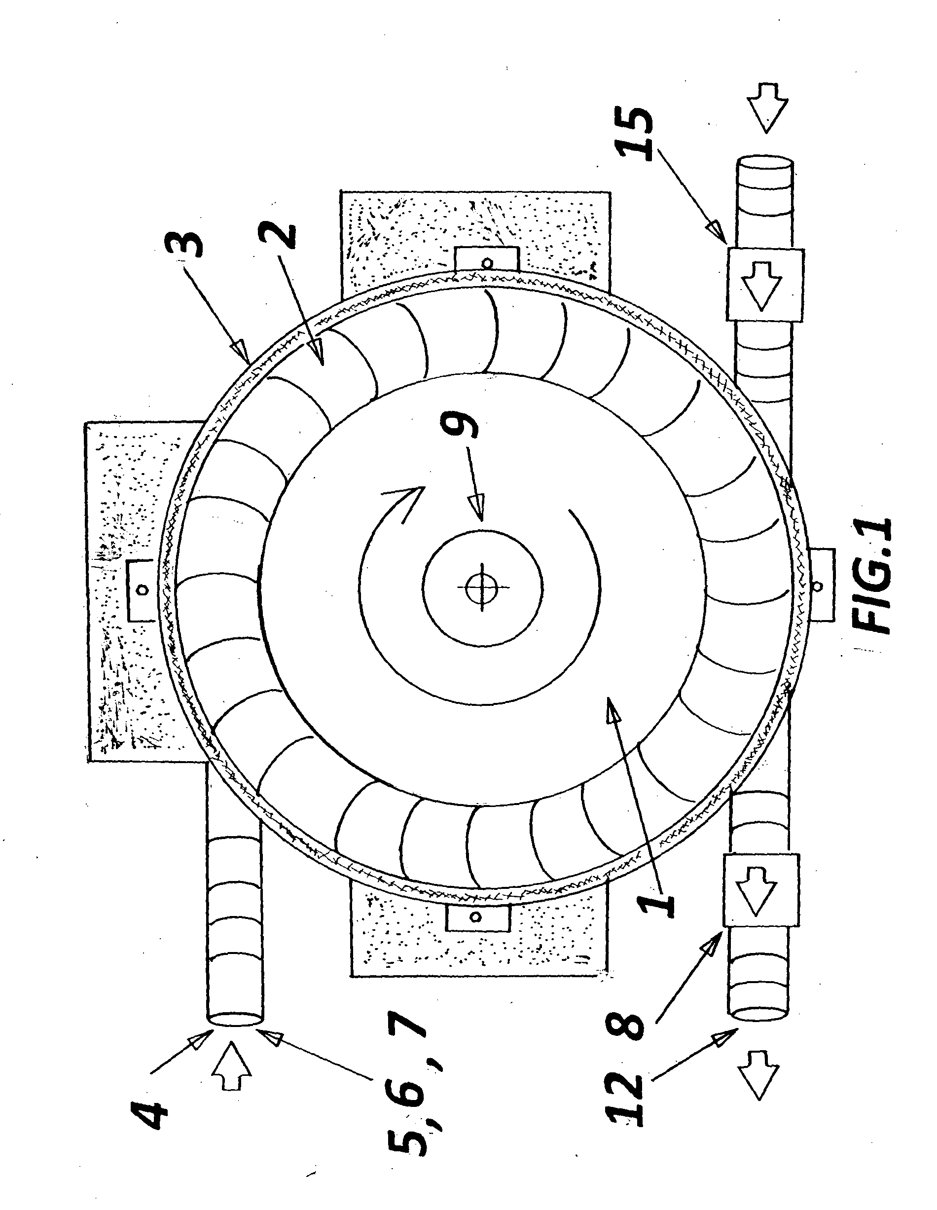
[0020]FIG. 1 illustrates an overhead view of the invented device. Shown is a flywheel (1) and turbine (2) assembly, surrounded by a casing (3). Shown is an air inlet (4) for compressed and high velocity air from a first blower (5), a second blower (6), or a third blower (7). A check valve (8) on the air outlet (12) directs the flow of the compressed and high velocity air in the proper direction, and prevents black flow. Bearings (9) for the flywheel and turbine (1,2) assembly reduces friction, and can be metal ball bearings, or compressed air bearings, or magnetic bearings (9). A vacuum lock (15) allows ambient air to enter the casing (3) when the kinetic energy is withdrawn from the flywheel (1) and turbine (2) assembly.

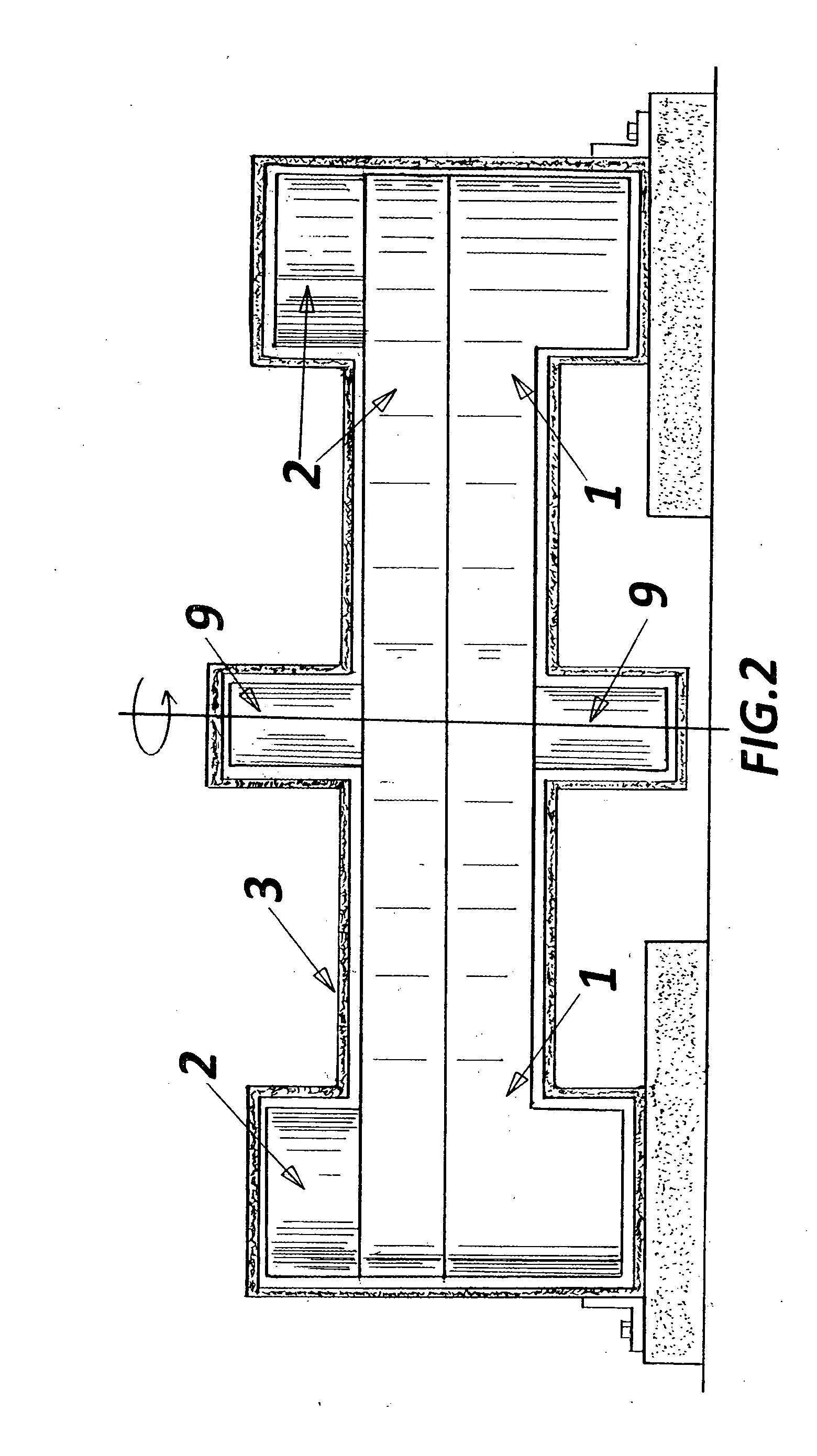
[0021]FIG. 2 illustrates a cross sectional view of the invented device. Shown is a flywheel (1) and turbine (2) assembly, inside a casing (3). Bearings (9) for the flywheel (1) and turbine (2) assembly can be metal ball bearings, or compressed air bearings, or magne...


PUM


Abstract

Developed is a blower to make compressed and high velocity air, using a solar powered electric blower, a wind powered blower, or a wind shroud. The compressed and high velocity air drives a turbine attached to a flywheel, thus overcoming the variability of wind and solar energy. Check valves are utilized. Thus providing compressed and high velocity air 24 hours a day, 7 days a week, year round. (68 words)

Description

FIELD OF INVENTION[0001]Developed is a blower powered by a photovoltaic cell, a wind turbine or a wind shroud, to drive a flywheel and turbine assembly.PRIOR ART[0002]Nix (U.S. Pat. No. 5,488,801, issued Feb. 6, 1996) illustrates the use of a photovoltaic cell to drive a electric fan for cooling air to a greenhouse.[0003]Nix (U.S. patent application Ser. No. 11 / 634,312, Filing date Dec. 5, 2006. Projected publication date Jun. 5, 2008) illustrates the use of flywheels for blowing compressed and high velocity air. FIG. 15 illustrates a electric motor driving a flywheel and a centrifuge blower. Paragraphs [0216] and [0196] describe the blower's operation.[0004]Nix (U.S. Pat. No. 8,776,785, issued Jul. 15, 2014) illustrates the utilization of a blower to move air through embedded pipes, heating the air via solar energy in a thermal mass.[0005]Nix (U.S. patent application Ser. No. 13 / 986,595, Filing date May 16, 2013. Projected publication date Nov. 20, 2014) illustrates the use of a so...

Claims


Application Information

Patent Timeline
IPC IPC(8): F04D25/02F04D25/04F01D15/08F04D25/16F04D29/42F03D9/00F04D17/08F04D25/06
CPCF04D25/024F04D17/08F04D25/045F04D25/06F05D2260/43F04D29/4206F03D9/001F01D15/08F05D2220/70F04D25/16F01D15/06F01D15/10F02C1/05F03G3/08F03G6/001F03G6/04F03G6/045F05B2260/421F05D2260/24F03D9/28H02S10/12H02S10/20Y02E10/46Y02E10/50Y02E10/72Y02E70/30F03D9/007F03D9/12F03D9/20F03D80/70
Inventor NIX, MARTIN EUGENE
Owner NIX MARTIN EUGENE
Learn More