Method of and apparatus for correcting for intensity deviations in a spectrometer

a technology of intensity deviation and intensity correction, applied in the field of calibrating a spectrometer, can solve the problems of unstable calibration, tedious and time-consuming tasks, etc., and achieve the effect of simple and reliable infrared spectroscopy

Active Publication Date: 2016-05-05
FOSS ANALYTICAL AS
View PDF3 Cites 3 Cited by
  • Summary
  • Abstract
  • Description
  • Claims
  • Application Information

AI Technical Summary

Benefits of technology

[0018]An additional advantage of the present inventive concept is that there is provided a method for detecting the pathlength deviation based on an individual spectrum of a sample, e.g. a reference fluid.
[0019]Yet another advantage of the present inventive concept is that there is no need for expertise in the art of handling the standardization sample. Also, the inventive method may be applied in operational environments which are less standardized. For instance, there may be weaker requirements on an allowed set of operational temperatures of the spectrometer.
[0020]Optionally, the pathlength deviation may be determined by determining a pluralit

Problems solved by technology

A problem with these spectrometers is that each of them needs to be calibrated, which may be a tedious and time consuming task.
However, d

Method used


Image

  • Method of and apparatus for correcting for intensity deviations in a spectrometer
  • Method of and apparatus for correcting for intensity deviations in a spectrometer
  • Method of and apparatus for correcting for intensity deviations in a spectrometer

Examples


Embodiment Construction

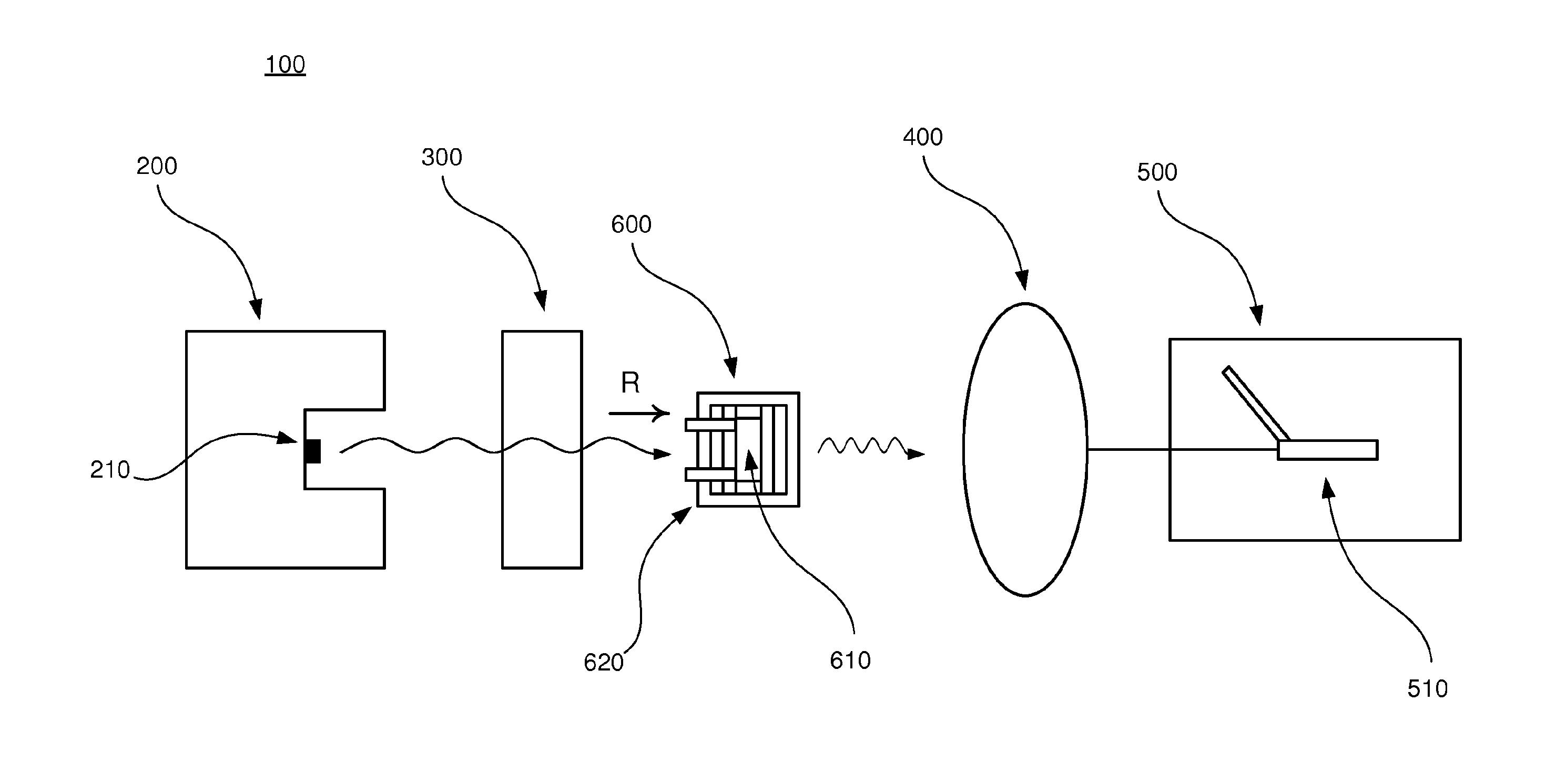
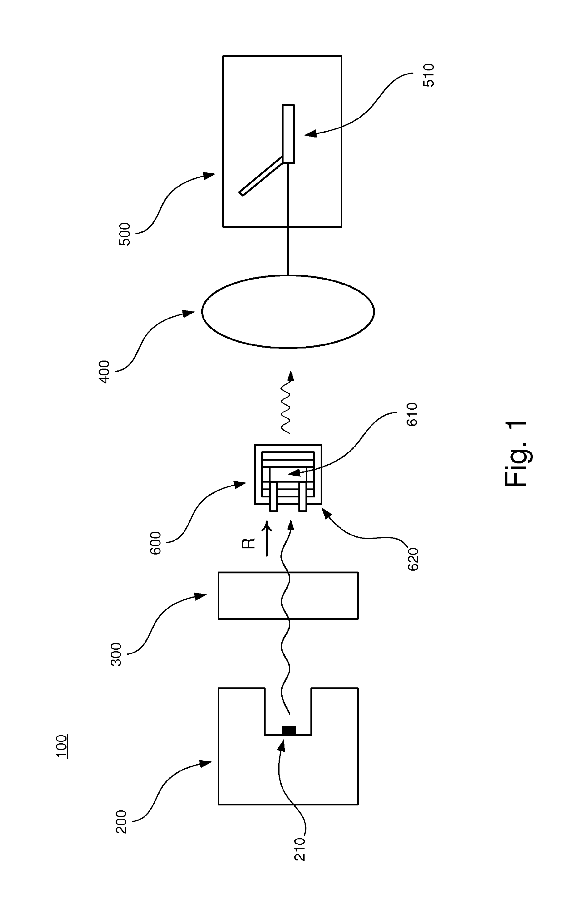
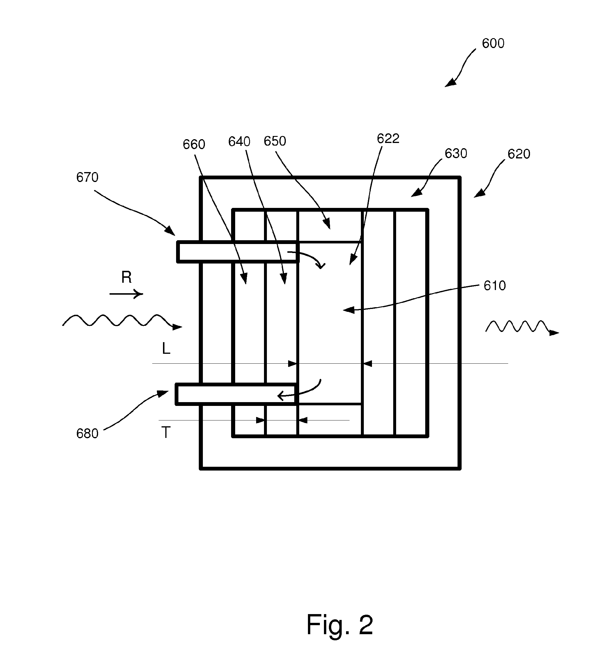
[0040]In the following, an embodiment of the inventive apparatus 100 will be described with reference to FIGS. 1 and 2 in the context of absorption spectroscopy. The apparatus 100 comprises a radiation device 200, an interferometric arrangement 300, a detector 400 and a measuring device 500. Also, a sample arrangement 600 to be analyzed is arranged to be placed in the apparatus 100.

[0041]The radiation device 200 comprises a radiation source 210 which is arranged to emit polychromatic infrared radiation in the direction as indicated by the letter R in FIGS. 1 and 2.

[0042]The interferometric arrangement 300 comprises necessary equipment for implementing Fourier transform spectroscopy, as is well-known to a person skilled in the art. For example, the interferometric arrangement 300 comprises a collimator which collimates the infrared radiation and additional equipment comprised in an interferometer, e.g optical components such as mirrors and lenses.

[0043]The detector 400 is arranged to...


PUM


Abstract

A method of determining a pathlength deviation of a sample (610), the method comprising: exposing the sample (610) to electromagnetic radiation at a plurality of wavenumbers, determining electromagnetic absorption in the sample (610) at the plurality of wavenumbers, determining a first wavenumber associated with a first absorption level of an absorption band and a second wavenumber associated with a second absorption level of the absorption band, wherein the second wavenumber is different from the first wavenumber, determining a difference between the first wavenumber and the second wavenumber, and determining the pathlength deviation based on the difference.

Description

FIELD OF THE INVENTION[0001]The present invention relates to a method for calibrating a spectrometer which determines an electromagnetic spectrum from a sample. More specifically, the present invention relates to a method of correcting for intensity deviations in a spectrometer.BACKGROUND Art[0002]Within the food industry, e.g. the dairy industry, it is often of vital importance to have knowledge about the characteristics of various food products, such as their chemical composition and their associated concentrations. One method of measuring these characteristics utilizes a spectrometer. The spectrometer typically measures the intensity of electromagnetic radiation which is transmitted through, or reflected by, a sample as a function of a collection of wavenumbers or wavelengths, or a wavenumber band, comprised in a particular region of the electromagnetic spectrum, such as the infrared part of the spectrum. The band wavenumber position may be used to identify the content in a sampl...

Claims


Application Information

Patent Timeline
IPC IPC(8): G01N21/35G01N21/27
CPCG01N21/35G01N21/274G01N2201/12746G01N2201/061G01N2021/3595G01J3/0291G01J3/42G01J3/45G01N21/31
Inventor HANSEN, PER WAABEN
Owner FOSS ANALYTICAL AS
Why Eureka
Try Eureka