

Calibration method based on dual-transmitting dual-receiving phase measurement and distance-measuring device thereof
a phase measurement and calibration method technology, applied in the field of photoelectric distance measurement, can solve the problems of shortened life, complicated circuit, and need for more precise apparatuses, and achieve the effect of reducing the lifetime of the device and reducing the cost of the devi
Inactive Publication Date: 2016-05-05
JIANGSU LAITZ OPTOELECTRONICS TECH
View PDF0 Cites 5 Cited by
- Summary
- Abstract
- Description
- Claims
- Application Information
AI Technical Summary
Benefits of technology
The present invention provides a calibration method that uses a dual-transmitting and dual-receiving path phase measurement to improve laser distance-measuring precision and stability. The system uses different filters and wavelengths to effectively separate inner and outer optical path, and reduce interference and crosstalk. This method can help to avoid uncertain phase noise caused by environmental changes and can cut system cost and strengthen application of laser distance measurement in all industries.
Problems solved by technology
Laser technologies as developed from laser have solved many technical problems that traditional technologies cannot solve.
The higher the precision of the laser distance-measuring instrument is, the more complicated its circuit is and the more precise apparatuses are needed.
(1) A single-transmitting and single-receiving system, namely, an optical signal transmitted via a single optical path and an optical signal received via a single optical path, and the inner and outer optical path be switched over by a controllable mechanical device, and phase calibration is performed by calculating phase values of the inner and outer optical path when switching over to eliminate an uncertain phase interference caused by the environment. Because of a mechanical switch, mechanical response time is long (generally an order of magnitude of several hundred milliseconds) so that real-time calibration cannot be performed, and furthermore the mechanical structure is relatively complicated which might easily come to mechanical wear and malfunction, and lead to a shortened lifetime. As a result, it is not suitable for working as an industrial precision instrument.
(2) A single-transmitting and dual-receiving system, namely, a light beam is transmitted via a signal optical path, and the inner optical path signal and the outer optical path signal are received respectively via the dual paths. The two signals received via the dual paths are processed respectively and are calculated for phase difference to eliminate an uncertain phase interference caused by the environment accordingly. The system uses two avalanche photo diodes (avalanche photo diode, APD) to receive the inner and the outer optical path signal respectively. Such dual-path amplifying circuit is apt to generate same-frequency interference. Furthermore, since avalanche voltage of each APD is different, the resultant phase shift is different. The avalanche voltage difference of APD needs to be limited less than 1V to ensure that the phase shift of different APDs are close. Therefore the requirement for APD is relative rigid and its production procedure is also increased.
(3) A conventional dual-transmitting and single-receiving system, namely, two light beams with the same wavelength are transmitted independently via dual optical paths, and the inner optical path signal and the outer optical path signal are sequentially received respectively by a receiving device. The two signals received via dual paths are processed respectively and are calculated for phase difference to eliminate an uncertain phase interference caused by the environment accordingly. The system generates two paths of optical wave signal with the same wavelength respectively by using two independent photoelectricity generating devices. Because two photoelectricity generating devices, especially two laser tubes, have the different working time of the inner and the outer optical path in operation, and because the above said principle cannot be used for eliminating different temperature drift extremely probably caused by the difference performance of the two lasers, a drift of the measured distance exist.
It is concluded that all of the above mentioned three solutions have drawbacks in practical application.
Method used
View moreImage
Smart ImageViewing Examples

Examples
first embodiment
[0036]FIG. 4 is a systematic block diagram of a distance-measuring apparatus employing a dual-transmitting and dual-receiving phase measurement calibration method according to the present invention;
second embodiment
[0037]FIG. 5 is a systematic block diagram of a distance-measuring apparatus employing a dual-transmitting and dual-receiving phase measurement calibration method according to the present invention;
[0038]FIG. 6 is a structural diagram of a distance-measuring apparatus employing a dual-transmitting and dual-receiving phase measurement calibration method according to an embodiment of the present invention.
Login to View More PUM
 Abstract
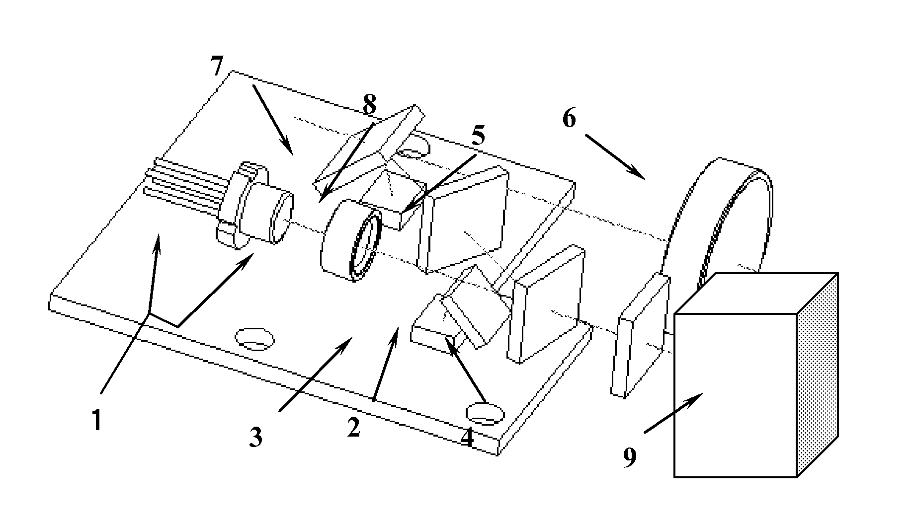
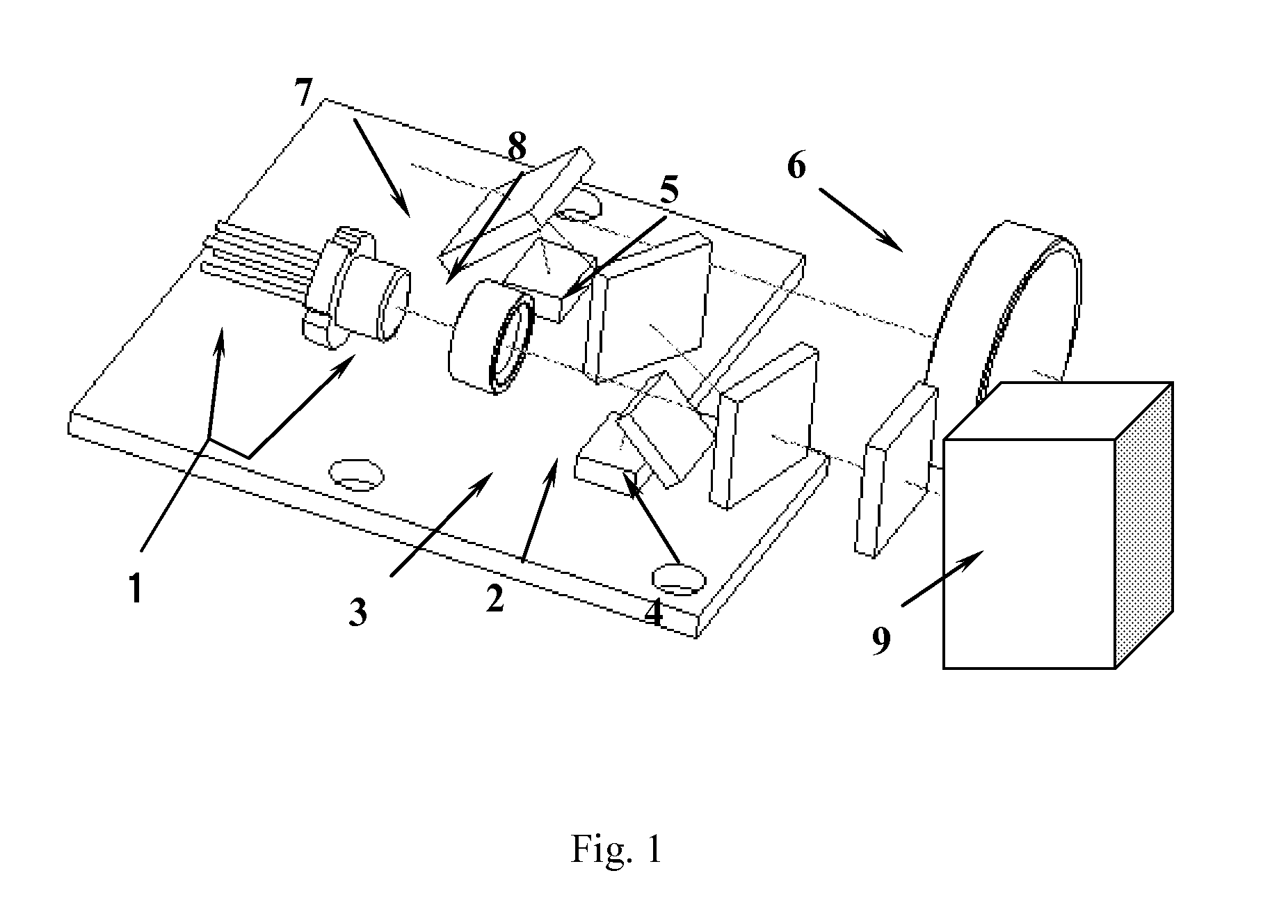
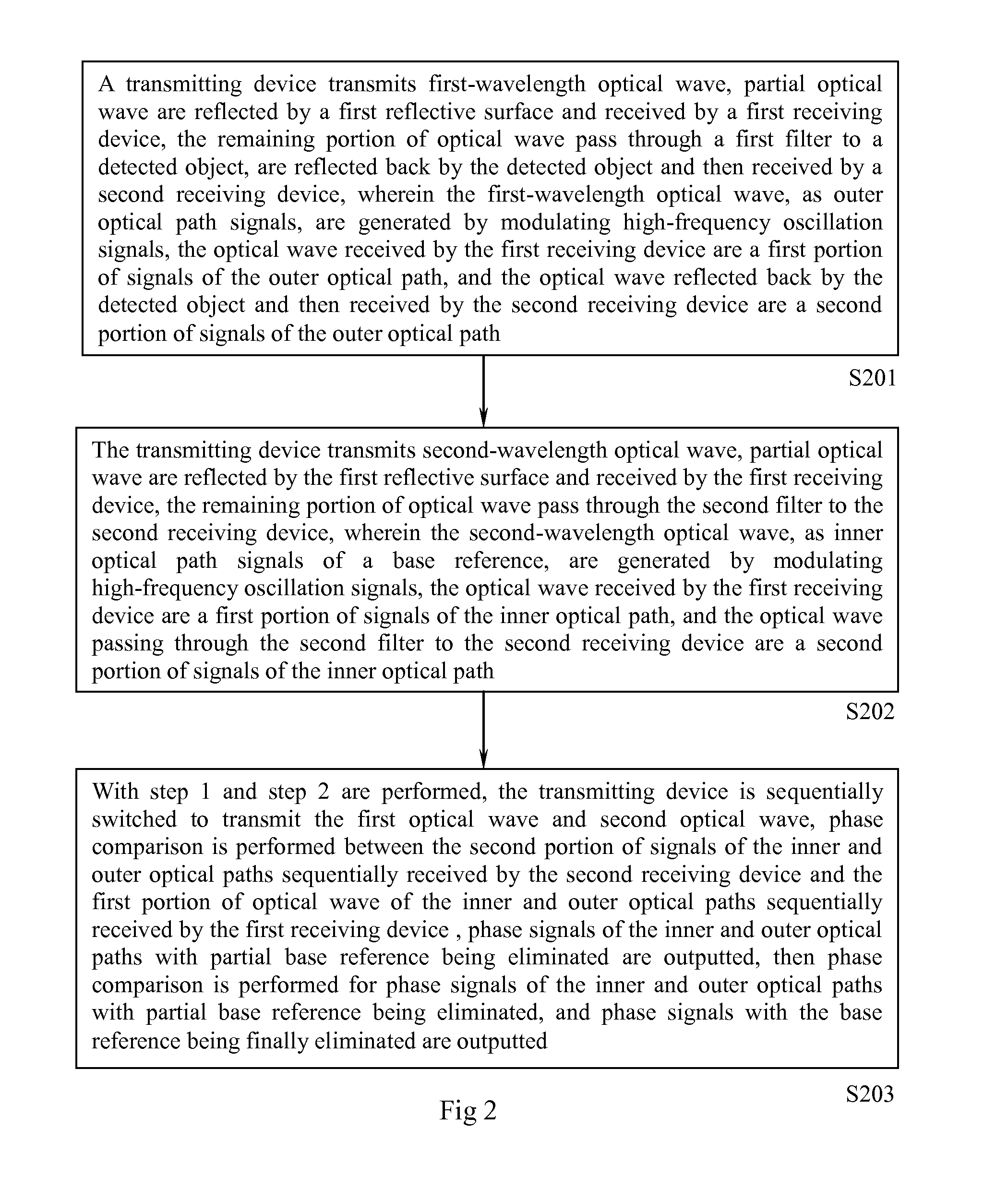
Provided are a calibration method based on dual-transmitting dual-receiving phase measurement and distance-measuring device, the calibration method comprising: step 1, forming an external optical path; step 2, forming an internal optical path; IN step 3, conducting a phase comparison between the second part of signals of the internal and external optical paths sequentially received by a second receiving device and the first part of signals of the internal and external optical paths sequentially received by a first receiving device, outputting two-way phase signals with part of a base reference being eliminated, conducting phase comparison again between the two-way signals with part of the base reference being eliminated, and outputting the final phase signal with the base reference being eliminated. The distance-measuring device comprises a transmitting device (1, 301, 403, 502), a first reflective surface (2, 302, 402, 503), a first receiving device (3, 506), a first filter (4, 304, 405, 504), a second filter (5, 305, 406, 505), a second receiving device (8, 507), and a phase detector (307, 411, 509). The calibration method and distance-measuring device realizes phase compensation and calibration, avoids introducing uncertain phase noise into a circuit due to environmental changes, improves distance-measurement precision, and reduces system costs.
Description
TECHNICAL FIELD[0001]The present invention relates to the field of photoelectric distance measurement, and particularly to a calibration method and a distance-measuring apparatus based on dual-transmitting and dual-receiving phase measurement system.BACKGROUND OF THE INVENTION[0002]Laser has been an invention that human beings fell proud and it has characteristics such as accuracy, quickness and convenience, easy use and strong anti-interference performance. Laser technologies as developed from laser have solved many technical problems that traditional technologies cannot solve.[0003]A laser range finder produced by integrating laser technologies with electronic technologies increasingly draws attention of industries such as civil use, military use and industrial concerning aspects such as length, height, distance, speed and shape measurement and has already been applied extensively to the following fields abroad: large industrial and mining enterprises, electrical power and petroch...
Claims
Login to View More Application Information
Patent Timeline
 Patent Type & AuthorityApplications(United States)
IPC IPC(8): G01S7/497G01S17/36G01S7/481
CPCG01S7/497G01S17/36G01S7/481
InventorDU, XINQIAO, BAIWENZHA, XIAOYILIU, XI
OwnerJIANGSU LAITZ OPTOELECTRONICS TECH