Transparent display including a screen with patterned light deflective elements

a technology of light deflective elements and transparent displays, applied in the field of transparent displays, can solve the problems of limit reliability and lifetime, and achieve the effects of limiting reliability and lifetime, large size, and easy scaling

Active Publication Date: 2016-05-05
SHARP KK
View PDF5 Cites 38 Cited by
  • Summary
  • Abstract
  • Description
  • Claims
  • Application Information

AI Technical Summary

Benefits of technology

[0015]The light deflective elements can be molded into a plastic screen or made as a sheet and laminated onto glass. They can be made simply by known cheap processes and contain no light sensitive material (in general, though the invention can have a phosphor as the deflecting element) which can limit reliability and lifetime. The invention can be scaled easily form small to very large size.
[0016]The light deflective element used will determine optical viewing angle and colour properties. For example, a roughened area on the plastic (that can be done easily using laser processing) used with a DLP colour wheel projector light source would have a wide angle of view with few colour problems.
[0017]The update rate from the display would depend only on the projector and this can easily be done with known image generation systems.
[0018]The screen gain for the transparency would be determined by the efficiency of the direction of light onto the light deflective elements and not into the clear areas. In principle the transparency would be 1−(area of element in unit cell) / (area of unit cell), and hence the screen gain for the transparency (as defined above) would then be (gain of elements alone)×(area of unit cell) / (area of element in unit cell), which can be significantly greater than one even if the elements are wide angle scattering and have a gain of less than 1. By using prism or holographic elements that direct light into a narrow angle (gain of elements already>1), the performance can be further enhanced.

Problems solved by technology

They can be made simply by known cheap processes and contain no light sensitive material (in general, though the invention can have a phosphor as the deflecting element) which can limit reliability and lifetime.

Method used


Image

  • Transparent display including a screen with  patterned light deflective elements
  • Transparent display including a screen with  patterned light deflective elements
  • Transparent display including a screen with  patterned light deflective elements

Examples


Embodiment Construction

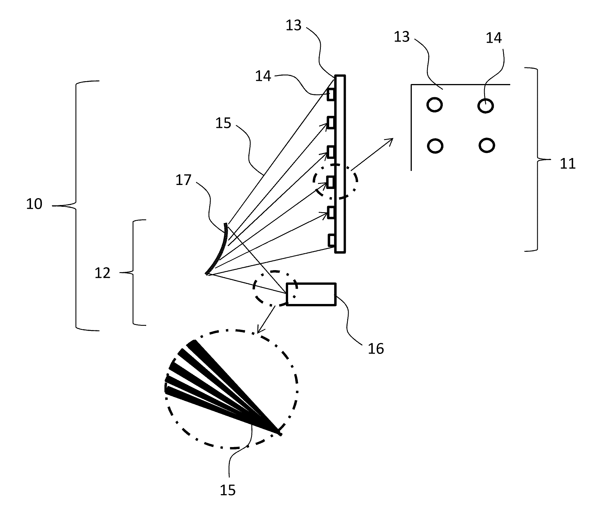
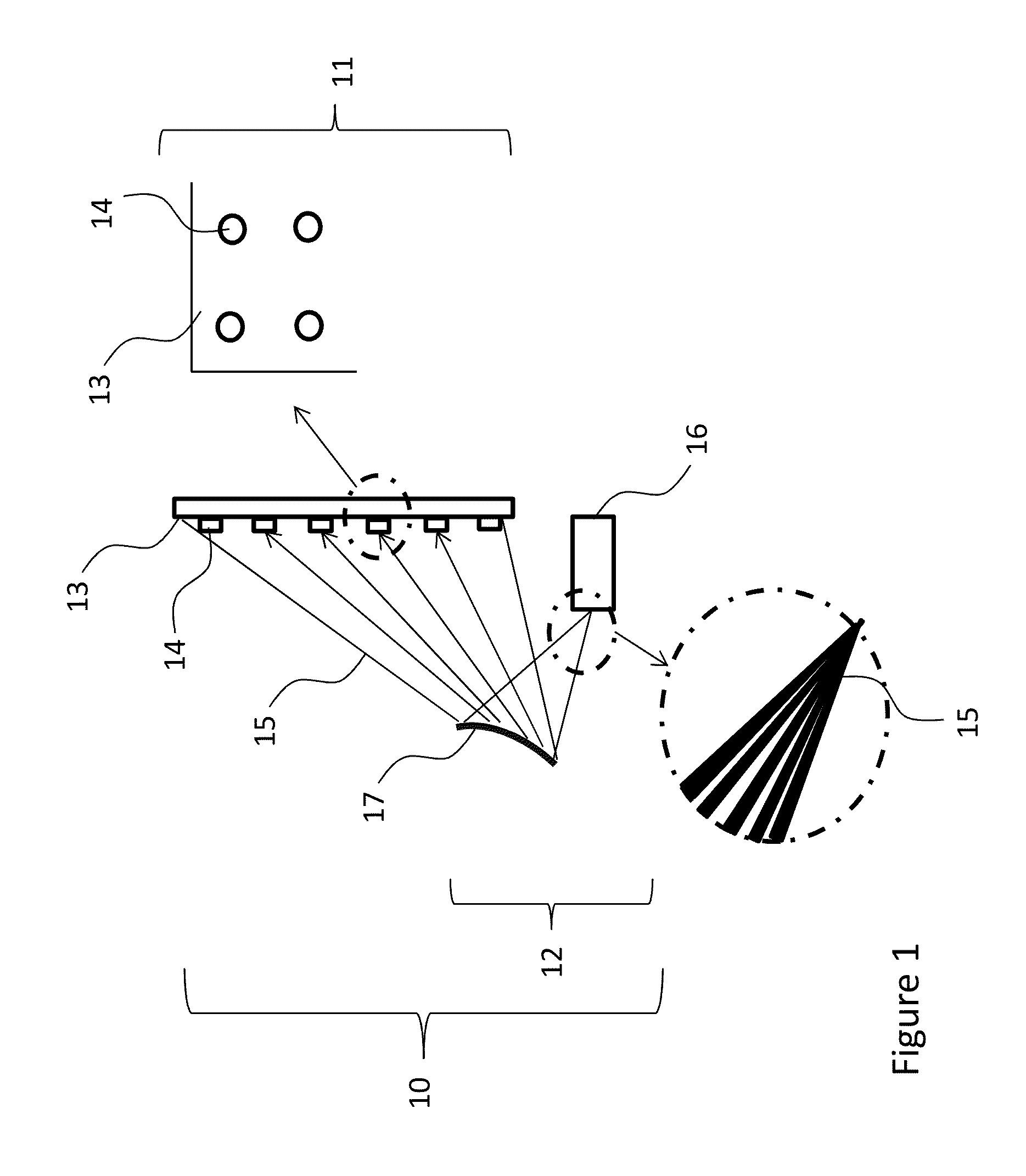
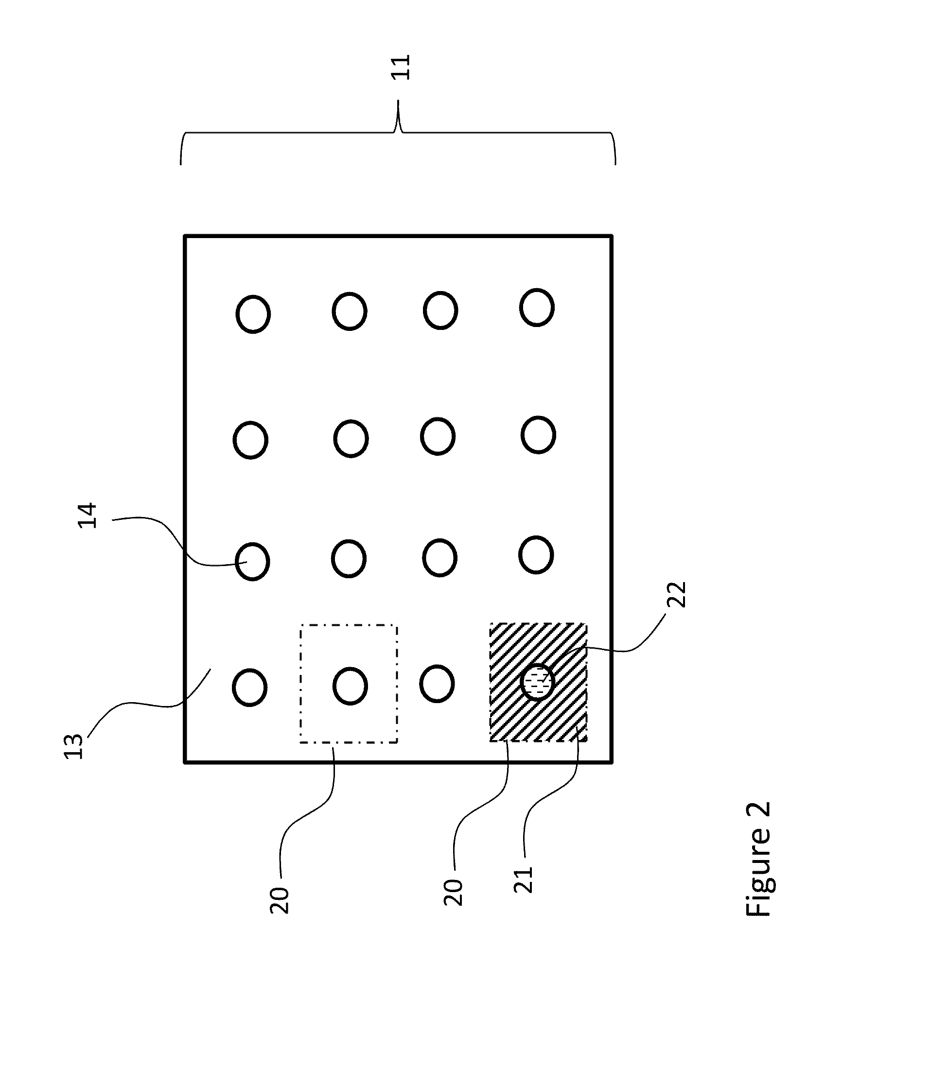
[0099]An aspect of the invention is a transparent display device. In exemplary embodiments, the display device includes at least one screen that has a plurality of light deflecting elements that are separated by transparent areas, and a projector device. The projector device is configured to direct light onto the light deflecting elements and not onto the transparent areas.

[0100]An exemplary embodiment of the present invention is described in connection with the depiction in FIG. 1. This embodiment constitutes a transparent display system 10 and includes a screen 11 and projector 12. The screen 11 has a clear transparent base material 13 that can be plastic (Poly (Methyl Methacrylate) [PMMA], polycarbonate, or like material) or glass. On the screen there exists a number of optical light deflecting elements 14 that are positioned with a spacing between each element. The projector 12 has a projection system 16 and reflector 17 in an “ultra short throw” arrangement where the thickness ...


PUM


Abstract

A transparent display device includes a screen that has a plurality of light deflecting elements that are separated by transparent areas, and a projector device. The projector device is configured to direct light onto the light deflecting elements and not onto the transparent areas. The display device may include a first screen and a second screen separated longitudinally relative to the projector, wherein each screen respectively has a plurality of light deflecting elements. The projector is configured to direct light onto the light deflecting elements and not onto the transparent areas of the two screens such that light from the first and second light deflecting elements appear in different virtual depth planes. Alternatively, a single screen may have first and second pluralities of light deflecting elements of different optical powers, such that light from the first and second light deflecting elements appear in different virtual depth planes.

Description

TECHNICAL FIELD[0001]The present invention concerns transparent displays for signage, advertising and other information requiring visualization of objects behind the display. Applications also include head-up displays and head-mounted displays for augmented reality applications.BACKGROUND ART[0002]Transparent displays are an increasingly interesting area for such applications as retail advertising and window displays. In particular, the use in a window requires a high level of transparency and the use as a retail display for perishable or light sensitive items (such as food or clothing) also requires a high transparency. A number of technologies have been suggested in order to achieve this aim. For example:[0003]Transparent displays based on LCD or OLED technologies are common but typically suffer from low overall transparency, below 40% in the case of LCDs and 60% for OLEDs. OLEDs are also difficult to make large and bright.[0004]Alternative technologies such as cholesteric LC or s...

Claims


Application Information

Patent Timeline
Patent Type & Authority Applications(United States)
IPC IPC(8): G03B21/625G02B13/16G09F19/18G03B21/28G02B27/22G02B3/00G02B13/22
CPCG03B21/625G02B3/0006G02B13/16G09F19/18G03B21/28G02B27/2221G02B13/22G09F9/302G03B21/10G03B21/60G03B21/62G02B3/0056G02B30/40
Inventor MONTGOMERY, DAVID JAMES
Owner SHARP KK
Why Eureka
Try Eureka