Sealing member, toner accommodating container and image forming apparatus

a technology of toner container and sealing member, which is applied in the direction of electrographic process apparatus, instruments, optics, etc., can solve the problems of difficulty in the mounting and demounting of toner bottles, the difficulty of conventional structures, and the raised or laterally deviated toner bottles, etc., to achieve simple structure, simple structure, and simple structure

Inactive Publication Date: 2016-05-05
YAMADA YUSUKE +4
View PDF4 Cites 12 Cited by
  • Summary
  • Abstract
  • Description
  • Claims
  • Application Information

AI Technical Summary

Benefits of technology

[0016]Accordingly, it is a principal object of the present invention to provide a sealing member in which a sealing member is locked with an image forming apparatus in order to open or unseal a toner discharge opening of a toner accommodating container, and yet the sealing member can be released from the image forming apparatus with a simple structure.
[0017]It is another object of the present invention to provide a toner accommodating container in which a locking portion of the toner accommodating container is locked with an image forming apparatus, and the locking of the locking portion with the image forming apparatus can be released with a simple structure.
[0018]It is a further object of the present invention to provide a toner accommodating container in which a sealing member is locked with an image forming apparatus to open or unseal

Problems solved by technology

However, the conventional structures involve some problems.
Therefore, there is a possibility that the toner bottle is raised or is laterally deviated with a result of improper rotation.
This imposes difficulty in the toner bottle mounting and demounting operations.
Additionally, the supplying system becomes complicated and expensive.
This degrades the developer supplying operativity, and even a slight deviation may result in inoperability.
This also results in complications and a cost increase.
However, the str

Method used


Image

  • Sealing member, toner accommodating container and image forming apparatus
  • Sealing member, toner accommodating container and image forming apparatus
  • Sealing member, toner accommodating container and image forming apparatus

Examples


embodiment 1

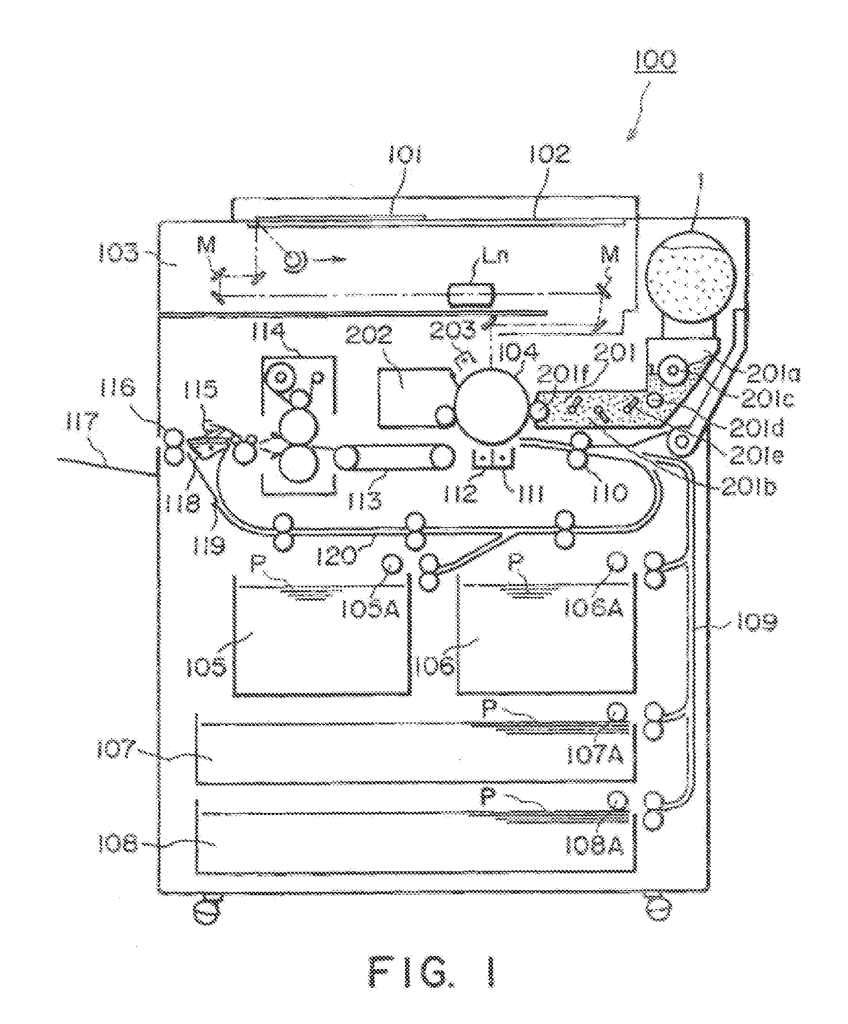
[0059]Referring to FIG. 1, a description will first be made as to an electrophotographic image forming apparatus which is an exemplary image forming apparatus which is mounted with a toner supply container (toner accommodating container) according to an embodiment of the present invention.

(Electrophotographic Image Forming Apparatus)

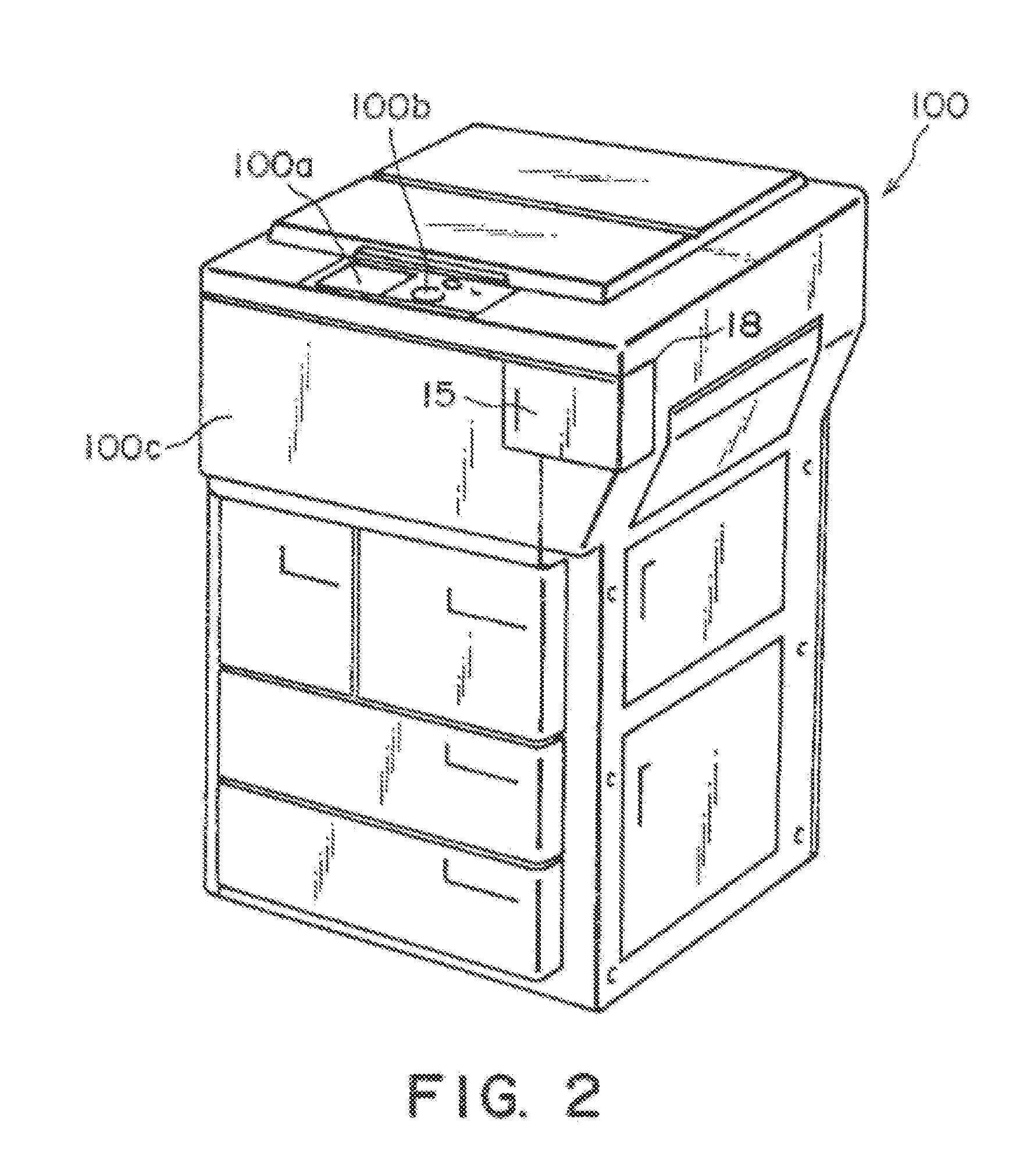
[0060]FIG. 1 shows an electrophotographic copying machine. An original 101 in a main assembly (main assembly of the apparatus) 100 is placed on an original supporting platen glass 102. A light image corresponding to the image information of the original 101 is an image on an electrophotographic photosensitive drum (image bearing member) 104 through a plurality of mirrors M and a lens Ln of an optical portion 103. On the basis of selection by the user on an operating portion 100a shown in FIG. 2 or on the basis of automatic selection in accordance with the paper size of the original 101, an optimum sheet P is selected from the cassettes 105, 106, 107, 108...

embodiment 2

[0167]Referring to FIGS. 23-25, and 32, a second embodiment of the present invention will be described. The same reference numerals as with the first embodiment are assigned to the elements having the corresponding functions, and a detailed description of the common structure is omitted for simplicity.

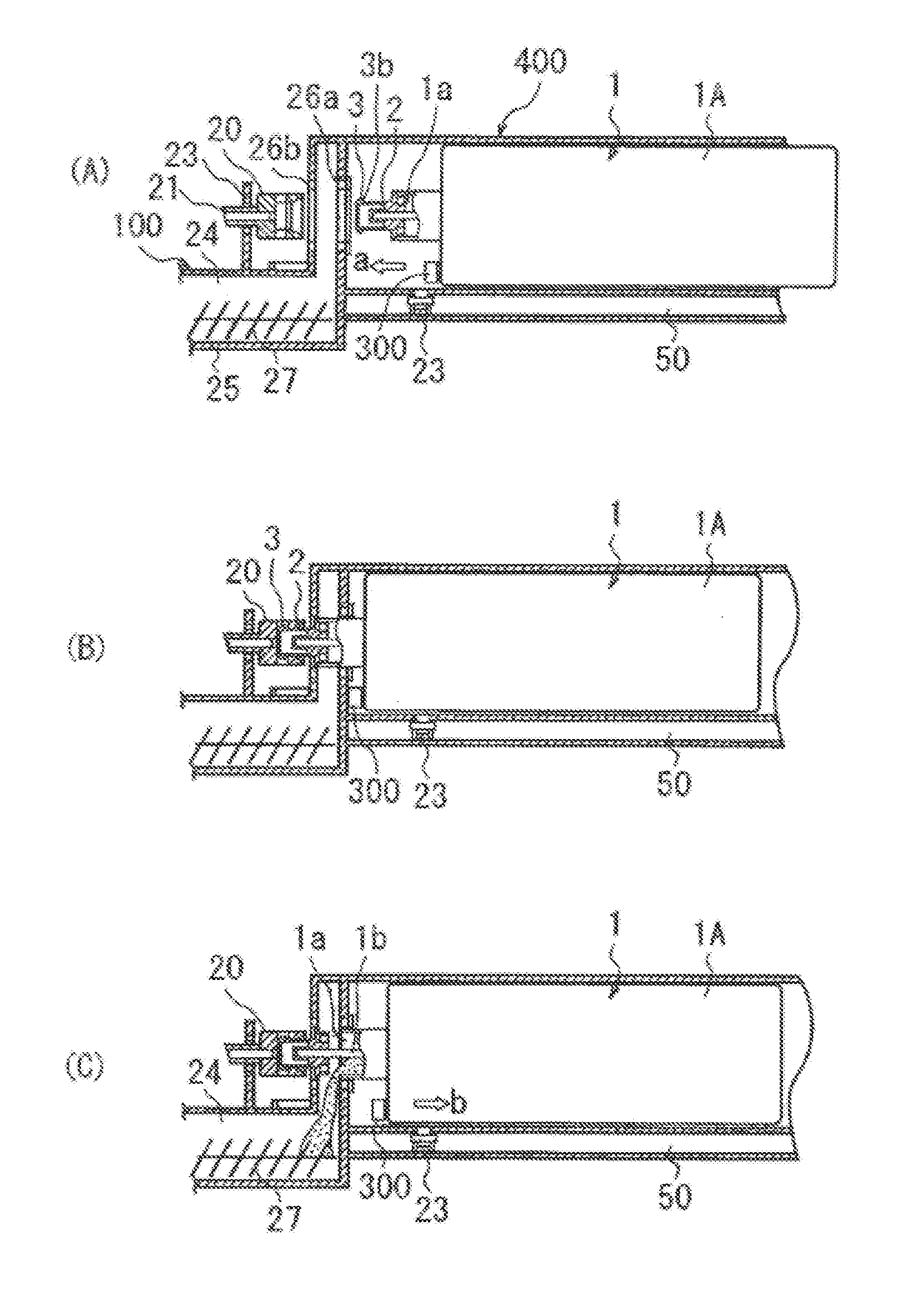
[0168]As shown in FIG. 23, in this embodiment, the releasing projection 4 (releasing portion) is provided on an outer surface not inside the cylindrical coupling engagement portion 2c of the sealing member 2 as in the first embodiment. In this embodiment, engaging projection 3 and the releasing portion 4 are provided at each of four circumferentially equidistant positions so as to constitute pairs. The structures of the driving portion 20 for locking engagement with the engaging projection of the sealing member are the same as with the Embodiment 1.

[0169]Correspondingly, the pushing member 21 is in the form of a cylinder covering the outside periphery of the driving portion 20 as shown...

embodiment 3

[0177]Referring to FIGS. 26 through 29, a third embodiment of the present invention will be described.

[0178]In the second embodiment, as shown in FIG. 24, the engaging projection 3 and the releasing portion (releasing projection) 4 for the sealing member 2 are provided at the outer surface of the engaging portion 2b. In this embodiment, as shown in FIG. 26, the engaging projection 3 and the releasing projection 4 are provided at each of four circumferentially equidistant positions on an inner surface of the engaging portion 2b.

[0179]Corresponding to such a structure of the sealing member 2, the main assembly driving portion 20 has a configuration shown in FIG. 27. The main assembly driving portion 20 comprises cylindrical portions including a free end portion 20b, a small diameter portion 20c, a large diameter portion 20d and a rear end 20e which have different outer diameters. It also comprises a through-hole 20f through which the pushing member 21 is penetrated. The inner diamete...


PUM


Abstract

A toner supply container includes a toner container body including a cylindrical portion and an opening, and a sealing member provided at one axial end portion of the container body. The sealing member is movable relative to the container body in an axial direction and includes a sealing portion provided at a side adjacent the container body and a coupling portion provided at a side remote from the container body. The coupling portion includes a supporting portion provided on the sealing portion, an engaging portion provided at a free end of the supporting portion, and a displacing force receiving portion provided on the supporting portion at a position closer to the container body than the engaging portion. The displacing force receiving portion is displaceable with the supporting portion and has a radially outermost part that is more remote from a rotation axis of the container body than a radially outermost part of the engaging portion. The supporting portion, the engaging portion, and the displacing force receiving portion are made of a plastic material.

Description

FIELD OF THE INVENTION AND RELATED ART[0001]This application is a divisional application of application Ser. No. 13 / 617,050, filed Sep. 14, 2012, which is a divisional application of application Ser. No. 13 / 231,388, filed Sep. 13, 2011, which issued as U.S. Pat. No. 8,290,394 on Oct. 16, 2012, which is a divisional application of application Ser. No. 12 / 981,785, filed Dec. 30, 2010, which issued as U.S. Pat. No. 8,045,901 on Oct. 25, 2011, which is a divisional application of application Ser. No. 12 / 615,012, filed Nov. 9, 2009, which issued as U.S. Pat. No. 7,890,027 on Feb. 15, 2011; which is divisional application of application Ser. No. 12 / 169,895, filed Jul. 9, 2008, which issued as U.S. Pat. No. 7,647,012 on Jan. 12, 2010; which is a divisional application of application Ser. No. 11 / 200,179, filed Aug. 10, 2005, which issued as U.S. Pat. No. 7,430,384 on Sep. 30, 2008; which is a divisional application of application Ser. No. 10 / 429,741 filed May 6, 2003, which issued as U.S. P...

Claims


Application Information

Patent Timeline
IPC IPC(8): G03G15/08
CPCG03G15/0898G03G15/0872G03G21/1676G03G2221/1684
Inventor YAMADA, YUSUKEBAN, YUTAKAMURAKAMI, KATSUYATAZAWA, FUMIOMINAGAWA, HIRONORI
Owner YAMADA YUSUKE
Why Eureka
Try Eureka