Check patentability & draft patents in minutes with Patsnap Eureka AI!

Burst optical signal transmission device and control method for burst optical signal transmission device

Active Publication Date: 2016-05-05
NIPPON TELEGRAPH & TELEPHONE CORP
View PDF30 Cites 10 Cited by
  • Summary
  • Abstract
  • Description
  • Claims
  • Application Information

AI Technical Summary

Benefits of technology

This patent is about a device and method to control a burst optical signal. The device can reduce the sudden changes in wavelength and light levels that occur during a burst signal and can help to stabilize the temperature control. This technology aims to improve the reliability and performance of the optical device.

Problems solved by technology

In contrast, large capacity over 10 Gb / s class might be required depending on a service such as a high-definition image service, a higher bit rate of the transmitter / receiver (40 or 100 Gb / s class) causes a sharp increase in cost of the transmitter / receiver, so that there is a problem that a practical system cannot be obtained.
However, in the direct modulation LD on which a temperature controlling element (TEC) is not mounted, an oscillation wavelength changes at a ratio of approximately 0.1 nm / degrees C. according to change in case temperature of the transceiver, so that large crosstalk between wavelength channels occurs.
Therefore, the DML without the TEC mounted cannot be applied to the NG-PON2.
However, when burst driving of such EML-TOSA is to be performed, two problems arise as follows.
A first problem is LD optical intensity fluctuation and oscillation wavelength fluctuation.
Such fluctuation was not problematic in the conventional PON in which the WDM technology was not introduced, but this causes the crosstalk between the wavelength channels in the NG-PON2, so that this might deteriorate reception sensitivity of the receiver in the NG-PON2.
In this manner, there is a practical problem in the burst driving of the EML-TOSA.
Other problems are unstable operation of a TEC control circuit.
In contrast, when the burst driving signal is applied to the LD unit, the bias current becomes approximately 50 mA and an amount of heat is drastically added such that the heat generation amount becomes approximately 75 to 100 mW, so that the feedback control of the ATC circuit becomes unstable and the temperature of the EML fluctuates.
Therefore, the burst driving of the EML-TOSA has a practical problem as the same as the first problem.

Method used


Image

  • Burst optical signal transmission device and control method for burst optical signal transmission device
  • Burst optical signal transmission device and control method for burst optical signal transmission device
  • Burst optical signal transmission device and control method for burst optical signal transmission device

Examples


first embodiment

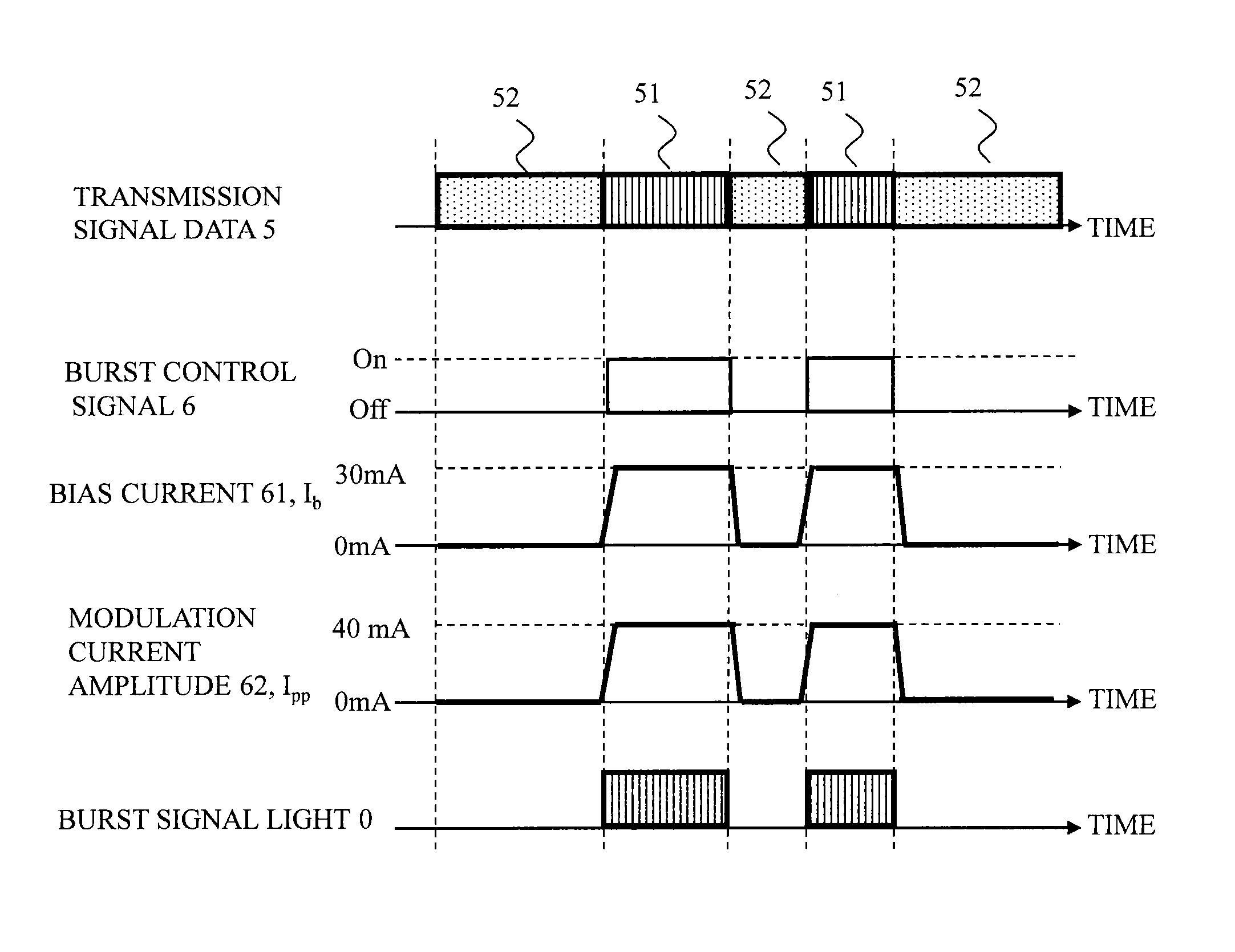
[0037]A burst optical signal transmission device of this embodiment is provided with an optical source which outputs continuous light, an external modulator which modulates the continuous light from the optical source based on a burst control signal indicating to output or stop transmission signal data and burst signal light to output the burst signal light, and an external modulator driving circuit which changes a bias level of the external modulator each time when the burst signal light is output and time when the burst signal light is stopped based on the burst control signal.

[0038]The optical source continuously outputs the continuous light of the same intensity.

[0039]Hereinafter, a control method for a 10 Gb / s class external modulator type burst optical signal transmission device for ONU of this embodiment is described in detail with reference to FIGS. 3 to 7. FIG. 3 illustrates a configuration of a burst optical signal transmission device for PON of this embodiment focusing on...

second embodiment

[0050]A burst optical signal transmission device of this embodiment is further provided with an optical source driving circuit which changes intensity of continuous light output from an optical source each time when burst signal light is output and time when the burst signal light is stopped based on a burst control signal.

[0051]A control method for a 10 Gb / s class external modulator type burst optical signal transmission device for ONU of this embodiment is hereinafter described in detail with reference to FIGS. 8 to 10. FIG. 8 illustrates a configuration of a burst optical signal transmission device for PON of this embodiment focusing only on a transmitting function of a transceiver 1 mounted on the ONU (receiving function and other peripheral circuits are not illustrated). FIG. 9 illustrates a time chart of the control method for the 10 Gb / s class external modulator type burst optical signal transmission device of this embodiment.

[0052]In FIG. 8, the burst optical signal transmis...


PUM


Abstract

A bias point of an external modulator is set to different values according to on and off of a burst control signal and an optical source is driven continuously in a burst optical signal transmission device. The burst optical signal transmission device avoid generation of transient fluctuation of a wavelength and a light amount at the time of burst signal rising.

Description

BACKGROUND[0001]1. Field of the Disclosure[0002]The present disclosure relates to a burst optical signal transmission device which transmits a burst optical signal and the like its a control method.[0003]2. Discussion of the Background Art[0004]Recently, along with rapid popularization of the Internet, a large capacity, advanced, and economical optical access system has been required. Research of a passive optical network (PON) is underway as a method of realizing such a system. The PON is an economically advantageous optical access communication system in which a plurality of users can share a transmission path between a center device and an optical passive element by concentrating a plurality of transmission paths from a plurality of users to a unique transmission path by the optical passive element such as an optical power splitter. In Japan, an economical optical access communication system Gigabit Ethernet (TM)-PON (GE-PON) in which up to 32 users share 1 Gb / s class line capaci...

Claims


Application Information

Patent Timeline
IPC IPC(8): H04B10/516H04B10/564
CPCH04B10/564H04B10/516H04B10/505
Inventor ASAKA, KOTATAGUCHI, KATSUHISANAKAMURA, HIROTAKA
Owner NIPPON TELEGRAPH & TELEPHONE CORP
Features
  • R&D
  • Intellectual Property
  • Life Sciences
  • Materials
  • Tech Scout
  • Unparalleled Data Quality
  • Higher Quality Content
  • 60% Fewer Hallucinations
Learn More