Agitator with oscillating weight element

a technology of agitator and weight element, which is applied in the direction of fluid removal, drilling accessories, borehole/well accessories, etc., can solve the problems of high fluctuating pressure drop, interference with data transmission, and expansion of drill strings, so as to reduce friction between drill strings and improve the weight transfer effect of drill strings

Inactive Publication Date: 2016-05-12
ADVANCETECH APS
View PDF4 Cites 10 Cited by
  • Summary
  • Abstract
  • Description
  • Claims
  • Application Information

AI Technical Summary

Benefits of technology

[0012]An object of the invention is to provide an agitator tool that reduces friction between the drill string and the inner wall of the bore hole and improves weight transfer from the drill string to the drill bit.

Problems solved by technology

This configuration has the disadvantage that it generates a high fluctuating pressure drop that interferes with the data transmission through the drilling fluid.
This configuration also has a temperature problem as the stator elastomer is limited by temperature.
This increased internal pressure causes the drill string to expand which will interfere with the data transmission through the drilling fluid.
The valves and openings formed in these tools are likely to plug due to the particles, solids and LCM in the drilling fluid which may cause the tool to fail due to the increasing internal pressure.
The valve openings formed in this tool are also likely to plug due to the particles and solids in the drilling fluid which may cause the tool to fail due to the increasing internal pressure.
This configuration has a relative complex structure with a lot of wearable parts which need to be cleaned or serviced at regular basis.
The agitator tool has a relative complex configuration with a large number of components that increase the risk of one or more components failing during operation, particularly the pivoting components.
This configuration delivers a hammer action to the system interfering with the data transmission through the fluid and provides very narrow passageway for the fluid to pass through the tool increasing the risk of blockages.

Method used


Image

  • Agitator with oscillating weight element
  • Agitator with oscillating weight element
  • Agitator with oscillating weight element

Examples


Embodiment Construction

[0061]In the following text, the figures will be described one by one and the different parts and positions seen in the figures will be numbered with the same numbers in the different figures. Not all parts and positions indicated in a specific figure will necessarily be discussed together with that figure.

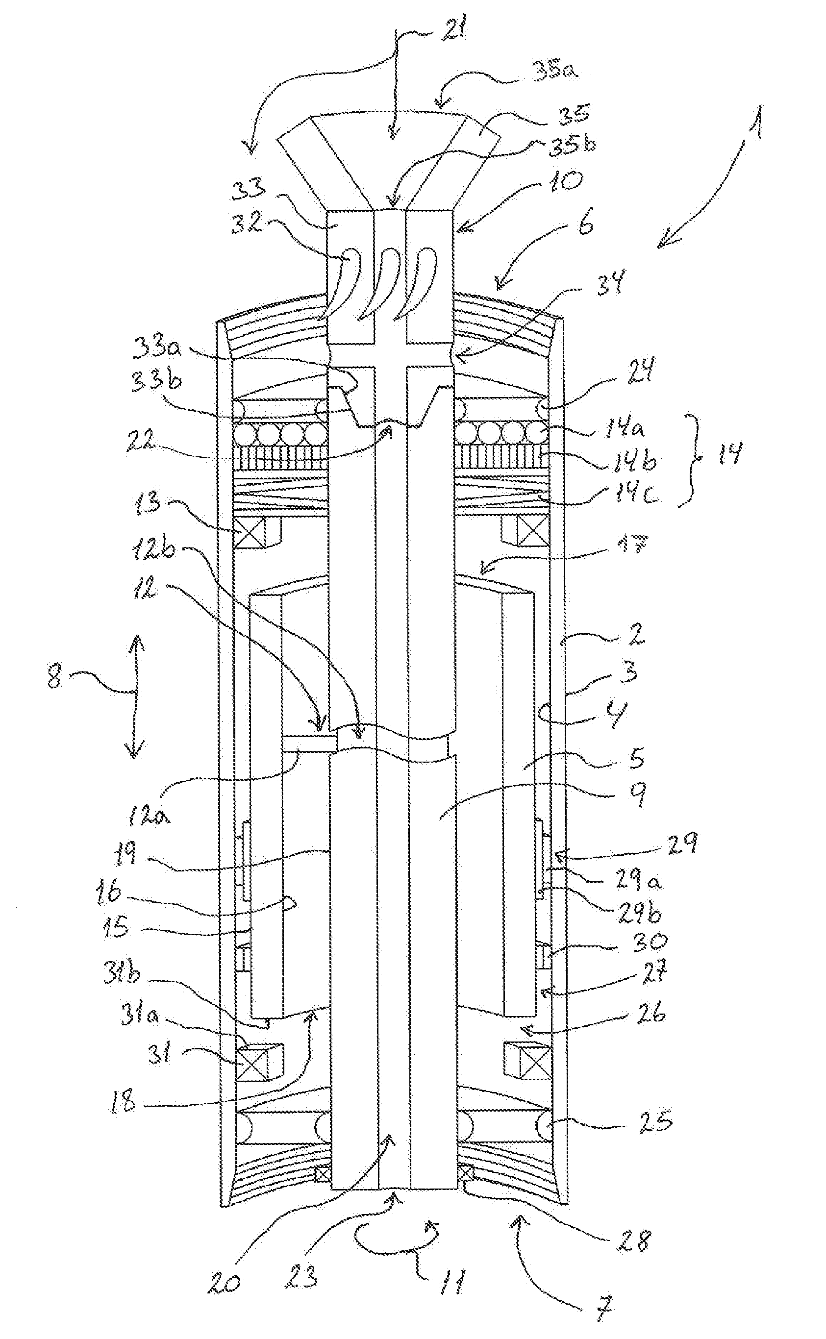
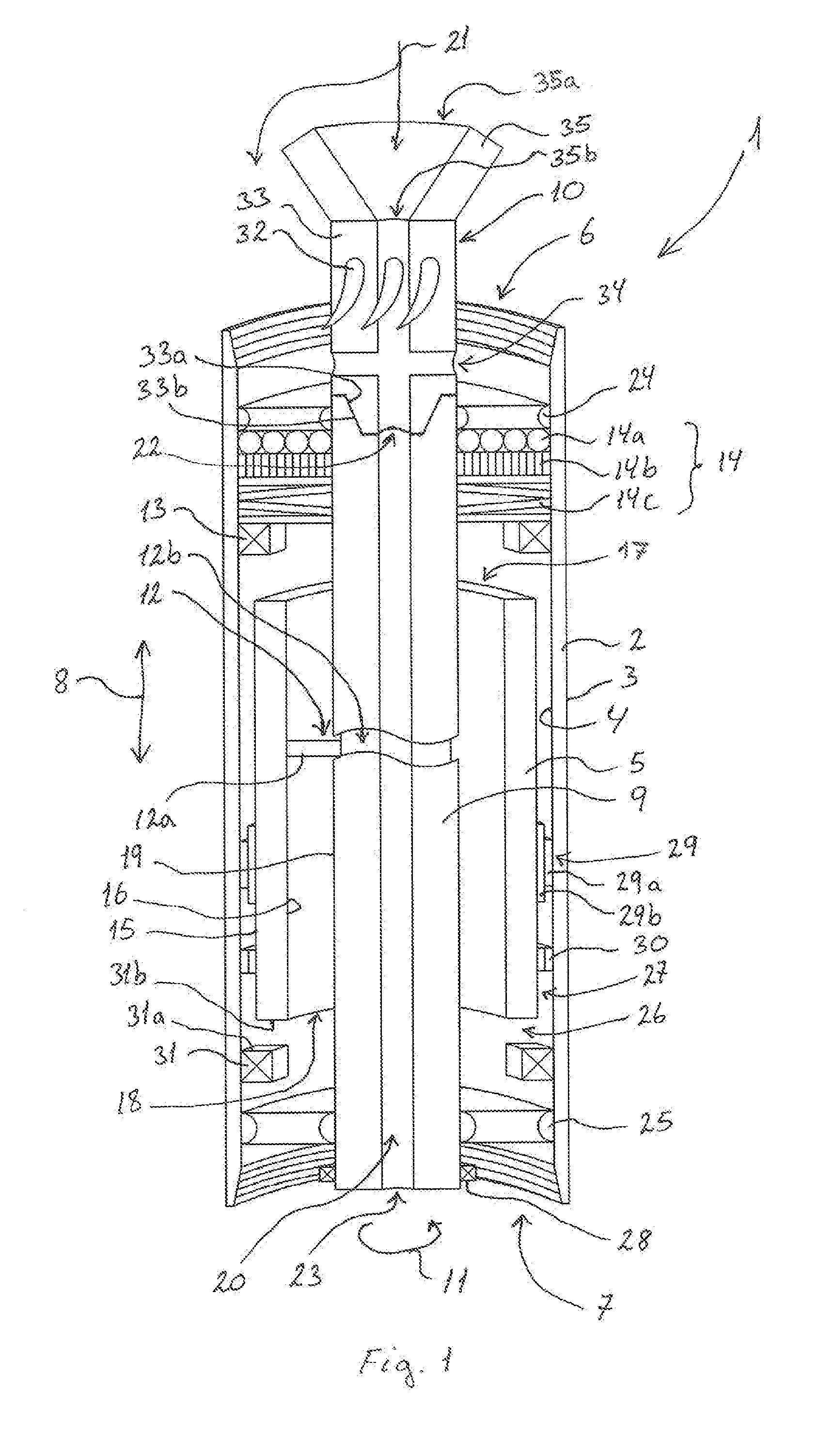
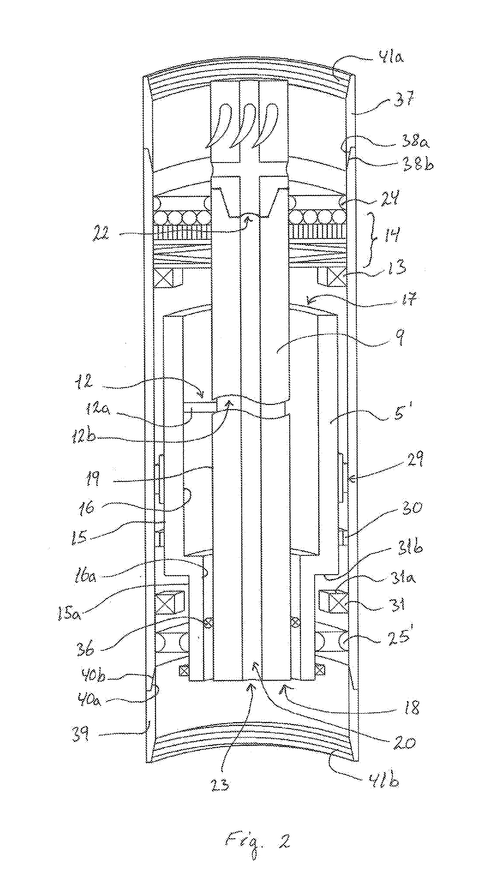
[0062]FIG. 1 shows a first exemplary embodiment of an agitator tool 1 for introducing axial movement in a downhole tool of a drill string in a bore hole (not shown). The agitator tool 1 may comprise a first housing 2 configured to be placed in the bore hole and which may have a cylindrical shape. The housing 2 has an outer surface 3 facing the inner surface of the bore hole and an inner surface 4 facing at least one moveable element 5 arranged inside the housing 2. The housing 2 may comprise a first open end 6 connected to a second open end 7 via the sides of the housing 2. The housing 2 may be made of a metal, such as steel, iron or another suitable material. The length and outer...


PUM


Abstract

An agitator tool (1) for introducing forward and backward axial movement in a downhole tool of a drill string, where the agitator tool has a first axially moveable element (5) coupled to a second laterally moveable element (9) arranged inside a housing (2) via mechanical coupling. The mechanical coupling may be a pin and groove arrangement where the groove forms a modified or unmodified sinus shaped guiding loop that allows the first element (5) to oscillate within the housing (2). The second element (9) is driven by a turbine unit which may have flow regulating means. This provides an agitator tool comprising with very few moving and wearable parts. The shape of the groove sections allows an accelerated and/or de-accelerated forward and backward movement of the first element (5) that allows it to be used for various applications in a bore hole.

Description

BACKGROUND OF THE INVENTION[0001]1. Field of the Invention[0002]The present invention relates to an agitator tool for introducing axial movement in a downhole tool, e.g., of a drill string in a bore hole, where the agitator tool comprises:a housing configured to be positioned in the bore hole, wherein the housing has a first open end connected to a second open end via at least an inner surface, wherein the housing is configured to guide at least a portion of a drilling fluid through the housing via the first and second open ends;a drive unit, e.g., a fluid activated drive unit, configured to drive the agitator tool, wherein the drive unit is configured to be coupled to a first moveable element arranged inside the housing; andwherein the first element is configured to move in an axial direction relative the housing for introducing axial movement in an external downhole tool coupled to the agitator tool when the drive unit drives the first element.[0003]2. Description of Related Art[0...

Claims


Application Information

Patent Timeline
Patent Type & Authority Applications(United States)
IPC IPC(8): E21B28/00
CPCE21B28/00E21B7/24E21B4/16
Inventor SOLEM, SIGURD
Owner ADVANCETECH APS
Why Eureka
Try Eureka