Sealing mechanism and turbo refrigerator

a sealing mechanism and refrigerator technology, applied in the direction of machines/engines, liquid fuel engines, light and heating apparatus, etc., can solve the problems of difficult to completely isolate the high pressure side and the low pressure side from each other, and achieve the effect of accurate centering of the sealing body, flexible deformation, and easy adjustment of the sealing body position

Active Publication Date: 2016-05-12
DAIKIN IND LTD
View PDF6 Cites 5 Cited by
  • Summary
  • Abstract
  • Description
  • Claims
  • Application Information

AI Technical Summary

Benefits of technology

[0019]According to the present invention, the sealing body surrounding the rotating shaft is supported by the sealing-body support part so as to be able to move in the radial direction of the rotating shaft, and the elastic member is interposed between the sealing body and the sealing-body support part. Such an elastic member can be flexibly deformed, and therefore, it is possible to easily adjust the position of the sealing body with respect to the rotating shaft. Accordingly, it is possible to accurately perform the centering of the sealing body with respect to the rotating shaft by the elastic member, and thus it becomes possible to make the gap between the sealing body and the rotating shaft narrower than that in the related art. Further, according to the present invention, even in a case where the rotating shaft comes into contact with the sealing body, impact due to the contact can be absorbed by the elastic member. Accordingly, it becomes possible to make the gap between the sealing body and the rotating shaft narrower than that in the related art. Therefore, according to the present invention, it becomes possible to improve sealing performance in a sealing mechanism which is disposed around a rotating shaft which is installed in a turbo refrigerator or the like.

Problems solved by technology

However, the impeller and the motor are connected by a rotating shaft for transmitting power, and therefore, it is difficult to completely isolate the high pressure side and the low pressure side from each other.

Method used


Image

  • Sealing mechanism and turbo refrigerator
  • Sealing mechanism and turbo refrigerator
  • Sealing mechanism and turbo refrigerator

Examples


Embodiment Construction

[0022]Hereinafter, an embodiment of a turbo refrigerator according to the present invention will be described with reference to the drawings. In addition, in the following drawings, in order to show each member in a recognizable size, the scale of each member is appropriately changed.

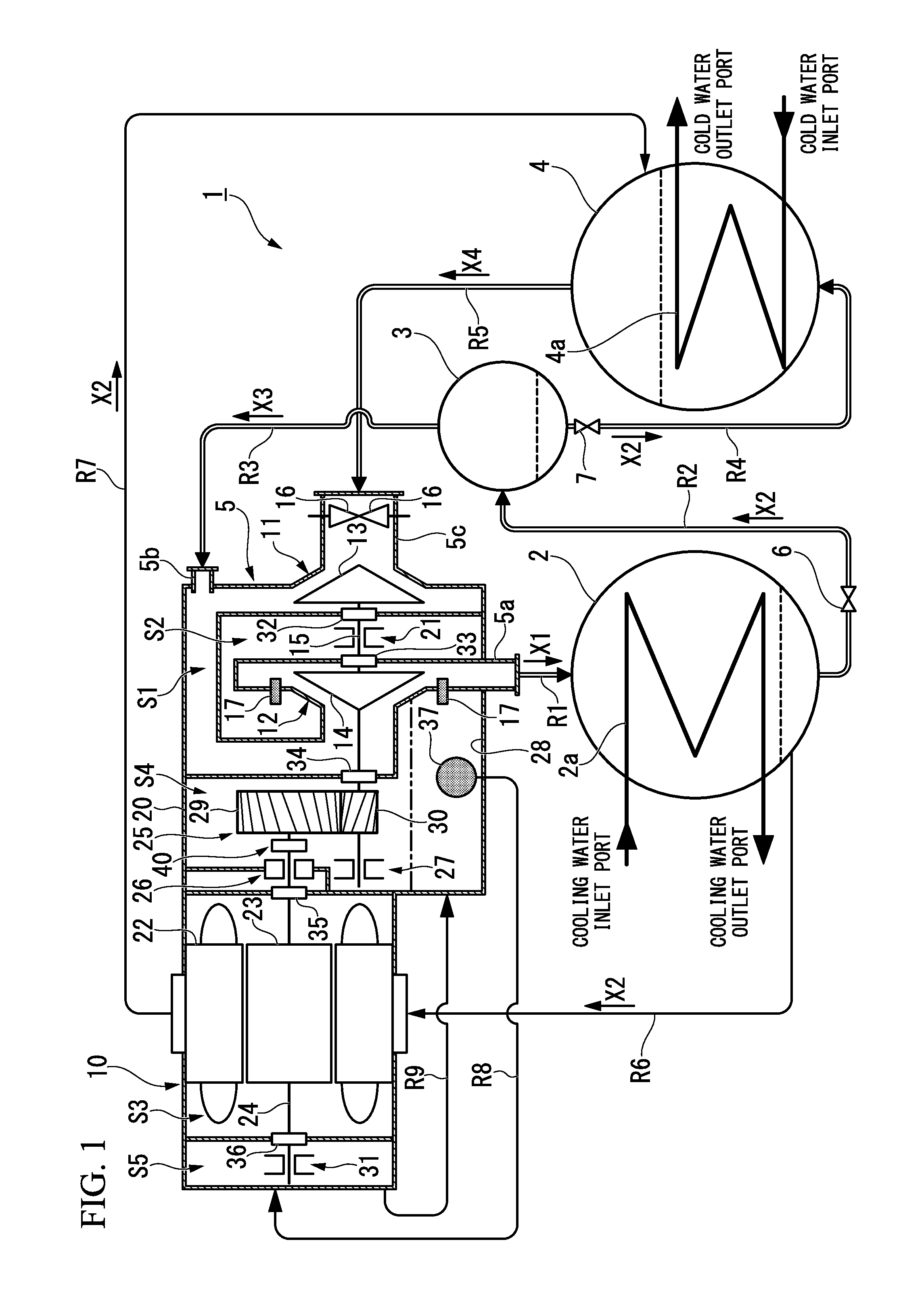
[0023]FIG. 1 is a system diagram of a turbo refrigerator 1 in an embodiment of the present invention. The turbo refrigerator 1 is provided with a condenser 2, an economizer 3, an evaporator 4, a turbo compressor 5, an expansion valve 6, and an expansion valve 7, as shown in FIG. 1.

[0024]The condenser 2 is connected to a gas discharge pipe 5a of the turbo compressor 5 through a flow path R1. A refrigerant (a compressed refrigerant gas X1) compressed by the turbo compressor 5 is supplied to the condenser 2 through the flow path R1. The condenser 2 liquefies the compressed refrigerant gas X1. The condenser 2 is provided with a heat exchanger tube 2a through which cooling water flows, and cools and liquefie...


PUM


Abstract

A sealing mechanism (40) includes: a ring-shaped sealing body (41) which surrounds a rotating shaft (24) when viewed from an axial direction; a sealing-body support part (42) which supports the sealing body (41) so as to be movable in a radial direction of the rotating shaft (24); and an elastic member (44) which is interposed between the sealing body (41) and the sealing-body support part (42).

Description

TECHNICAL FIELD[0001]The present invention relates to a sealing mechanism and a turbo refrigerator.[0002]Priority is claimed on Japanese Patent Application No. 2013-117738, filed on Jun. 4, 2013, the content of which is incorporated herein by reference.BACKGROUND ART[0003]For example, in a turbo refrigerator which is provided with a turbo compressor having a motor and an impeller, a refrigerant is compressed by the impeller, and therefore, the impeller side has a high pressure and the motor side relatively has a low pressure. If such a pressure difference is generated, gas leaks out from the high pressure side to the low pressure side, and therefore, it is necessary to perform sealing by a sealing mechanism. However, the impeller and the motor are connected by a rotating shaft for transmitting power, and therefore, it is difficult to completely isolate the high pressure side and the low pressure side from each other.[0004]Therefore, as shown in, for example, Patent Document 1, in ge...

Claims


Application Information

Patent Timeline
Patent Type & Authority Applications(United States)
IPC IPC(8): F04D29/12F25B1/053F16J15/447
CPCF04D29/122F25B1/053F16J15/447F16J15/44F04D29/102F04D29/624F25B1/10F25B2400/13F25B2500/22F04D29/668
Inventor ODA, KENTAROUSAKUMA, NOBUYOSHI
Owner DAIKIN IND LTD
Why Eureka
Try Eureka