Control device for vehicle

a control device and vehicle technology, applied in mechanical equipment, instruments, gearboxes, etc., can solve the problems of internal combustion engine inability to drive in an operation range where fuel can be saved, degrade the transmission efficiency of transmitting torque via fluid, and reduce the power loss caused by rotation of output shaft with transmission mechanism, so as to reduce the power loss, dampen the torsional vibration, and reduce the effect of vibration

Active Publication Date: 2016-05-12
TOYOTA JIDOSHA KK
View PDF1 Cites 17 Cited by
  • Summary
  • Abstract
  • Description
  • Claims
  • Application Information

AI Technical Summary

Benefits of technology

[0016]According to the invention, in the case where the torque is transmitted from the internal combustion engine to the drive wheels via the continuously variable transmission, the transmission mechanism is in a state that does not constitute the torque transmission path stretching from the internal combustion engine to the drive wheels and can rotate idle. The transmission mechanism is joined to the output shaft by the other clutch, and the transmission mechanism can function as a rotational inertia body. That is, the transmission mechanism, which is a functional mechanism for forming the torque transmission path, can be used as a functional mechanism for dampening a vibration. Accordingly, the vibration that is originated from the internal combustion engine and is transmitted to the torque transmission path including the continuously variable transmission can be dampened by inertial moment related to the transmission mechanism. Thus, noise, such as booming noise, generated by the vibration and a front-rear vibration and an up-down vibration of the vehicle can be suppressed.
[0018]Accordingly, either one of the clutches can be brought into an engaged state in accordance with an operation state in a case where the speed of the internal combustion engine becomes at most equal to the specified speed, a case where the output torque of the internal combustion engine becomes at least equal to the specified torque, a case where the transmission gear ratio by the continuously variable transmission is at most equal to the specified transmission gear ratio, or the like during a travel by the continuously variable transmission. That is, in the operation state where the vibration that is transmitted to the torque transmission path including the continuously variable transmission becomes relatively large, the vibration can effectively be dampened by an inertial force by the transmission mechanism that is coupled to the output shaft. In addition, in accordance with the operation state, the other clutch can be disengaged, so as to decouple the transmission mechanism from the output shaft. In this way, power loss that is caused by rotation of the output shaft with the transmission mechanism can be suppressed. In other words, the transmission mechanism is coupled to the output shaft in an operation range where the vibration originated from the internal combustion engine is relatively large as in the above-described operation state. On the other hand, in an operation range where the vibration is relatively small, the transmission mechanism can be controlled so as to be decoupled from the output shaft. That is, it is possible to dampen a torsional vibration and improve fuel economy by using the transmission mechanism as the rotational inertia body.
[0019]In addition, according to the invention, the transmission mechanism is constituted as the speed reduction mechanism in the torque transmission path that stretches from the internal combustion engine to the drive wheels. In other words, in the case where the torque transmission path that includes the transmission mechanism is seen in a direction from the output shaft toward the input shaft, the transmission mechanism is constituted as a speed increase mechanism. Accordingly, in the case where the transmission mechanism is coupled to the output shaft during the travel by the continuously variable transmission, the torque of the output shaft is applied to the transmission mechanism, and the transmission mechanism generates a speed increasing action from the output shaft side to the input shaft side. That is, the transmission gear ratio (a speed increase gear ratio) of the transmission mechanism in the case where the transmission path that includes the transmission mechanism is seen in the direction from the output shaft side toward the input shaft side has a small value. Thus, equivalent inertial moment that is related to the transmission mechanism and acts on the output shaft obtains a large value. In other words, the equivalent inertial moment that is based on the transmission gear ratio by the transmission mechanism can effectively be used as the inertial force that acts on the output shaft by using the transmission gear ratio (the speed reduction gear ratio) of the transmission mechanism that is constituted as the speed reduction mechanism in the torque transmission path stretching from the internal combustion engine to the drive wheels. In addition, there is no need to increase weight of a unit, such as the continuously variable transmission or the transmission mechanism, so as to increase the inertial moment that acts on the torque transmission path. Accordingly, the increase in size of the powertrain can be prevented.
[0020]Furthermore, according to the invention, the transmission path that includes the transmission mechanism includes the forward / reverse travel switching mechanism that is constructed of the planetary gear unit. Accordingly, the inertial moment by the forward / reverse travel switching mechanism can act on the output shaft by engaging the clutch that is arranged on the downstream side in the torque transmission path. The torsional vibration can also effectively be dampened by increasing equivalent inertial moment related to the output shaft. In addition, since the clutch on the downstream side is constructed of the meshing-type clutch, the inertial moment of the transmission mechanism can reliably act on the output shaft by meshing the clutch. Furthermore, a control structure for controlling actuation of the meshing-type clutch can be prevented from being complicated, and thus coupling or decoupling between the transmission mechanism and the output shaft can be controlled with the simple control structure.

Problems solved by technology

In this case, vibrations and noise, such as front-rear and up-down vibrations of the vehicle and booming noise in a vehicle cabin, are possibly generated due to a vibration that is generated by explosion of fuel in the internal combustion engine, that is, transmission of a vibration that is generated when the internal combustion engine outputs torque to the torque transmission path.
However, in the configuration described in above-described JP 62-45455 U, while it is possible to suppress transmission of the vibration, which is generated when the internal combustion engine outputs the torque, to the torque transmission path by a fluid transmission device, transmission efficiency for transmitting the torque via the fluid is degraded.
Supposedly, in the case where the speed of the internal combustion engine is increased so as to dampen the vibration transmitted to the torque transmission path, the internal combustion engine cannot be driven in an operation range where the fuel can be saved.
Accordingly, while the vibration can be dampened, the fuel economy is possibly degraded.
In addition, in the case where the mass of the flywheel is increased, the vibration transmitted to the torque transmission path can be dampened by the inertial moment of the flywheel.
However, in conjunction with an increase in the mass of the flywheel, an inertial force in the torque transmission path is increased, and the fuel economy is thereby degraded.
Furthermore, a powertrain is increased in size due to an increase in weight of the unit.

Method used


Image

  • Control device for vehicle
  • Control device for vehicle
  • Control device for vehicle

Examples


Embodiment Construction

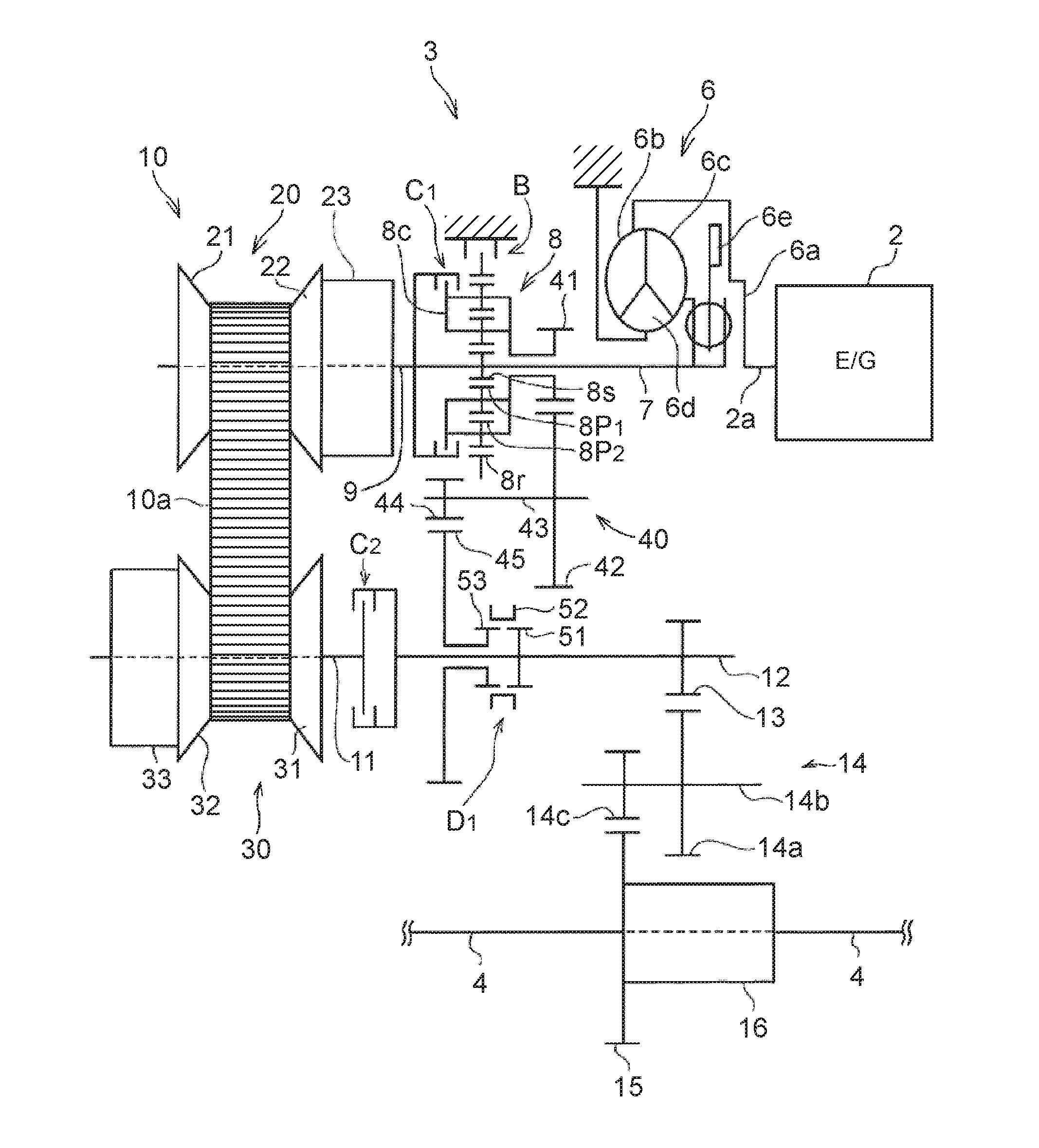
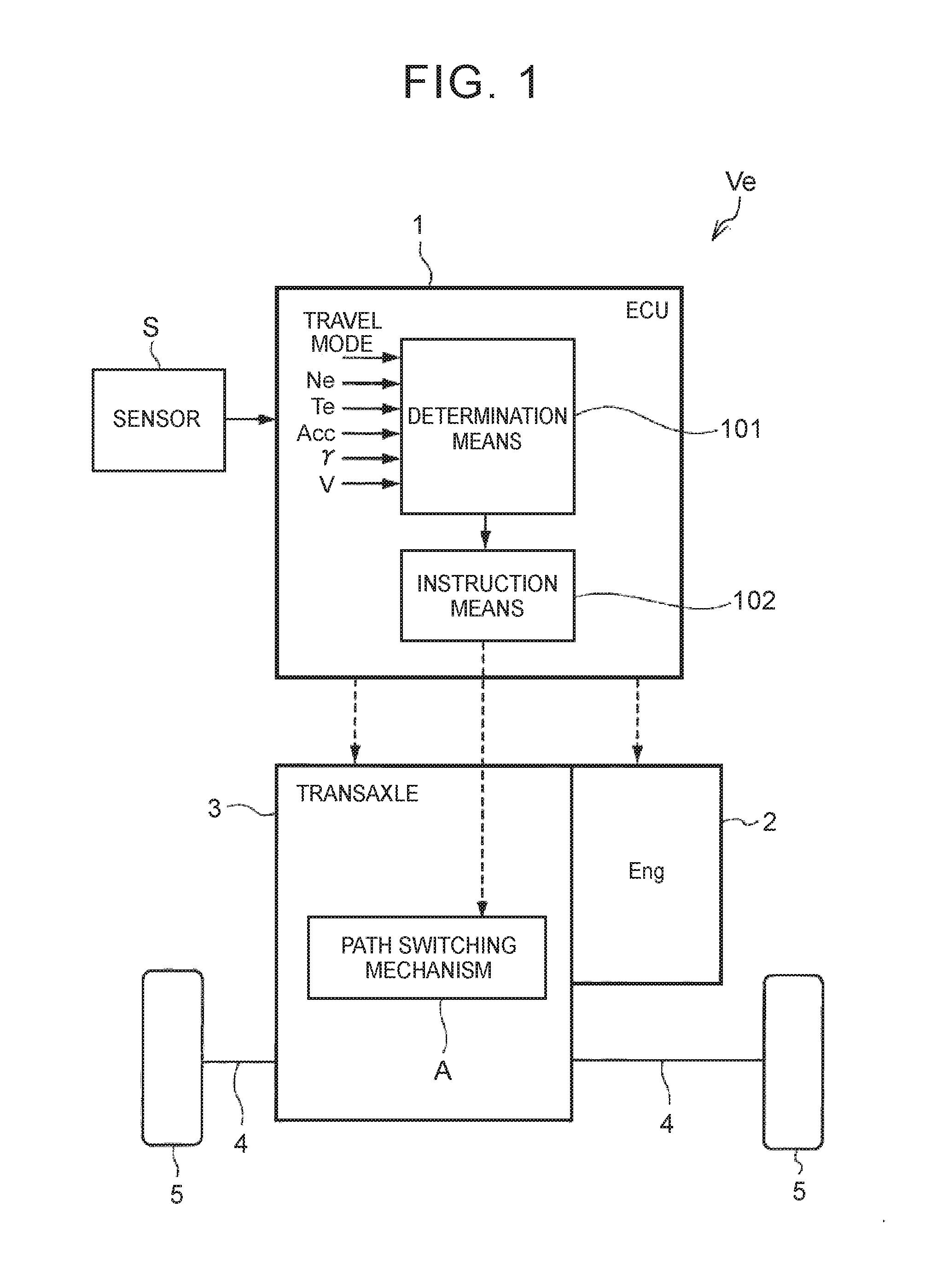
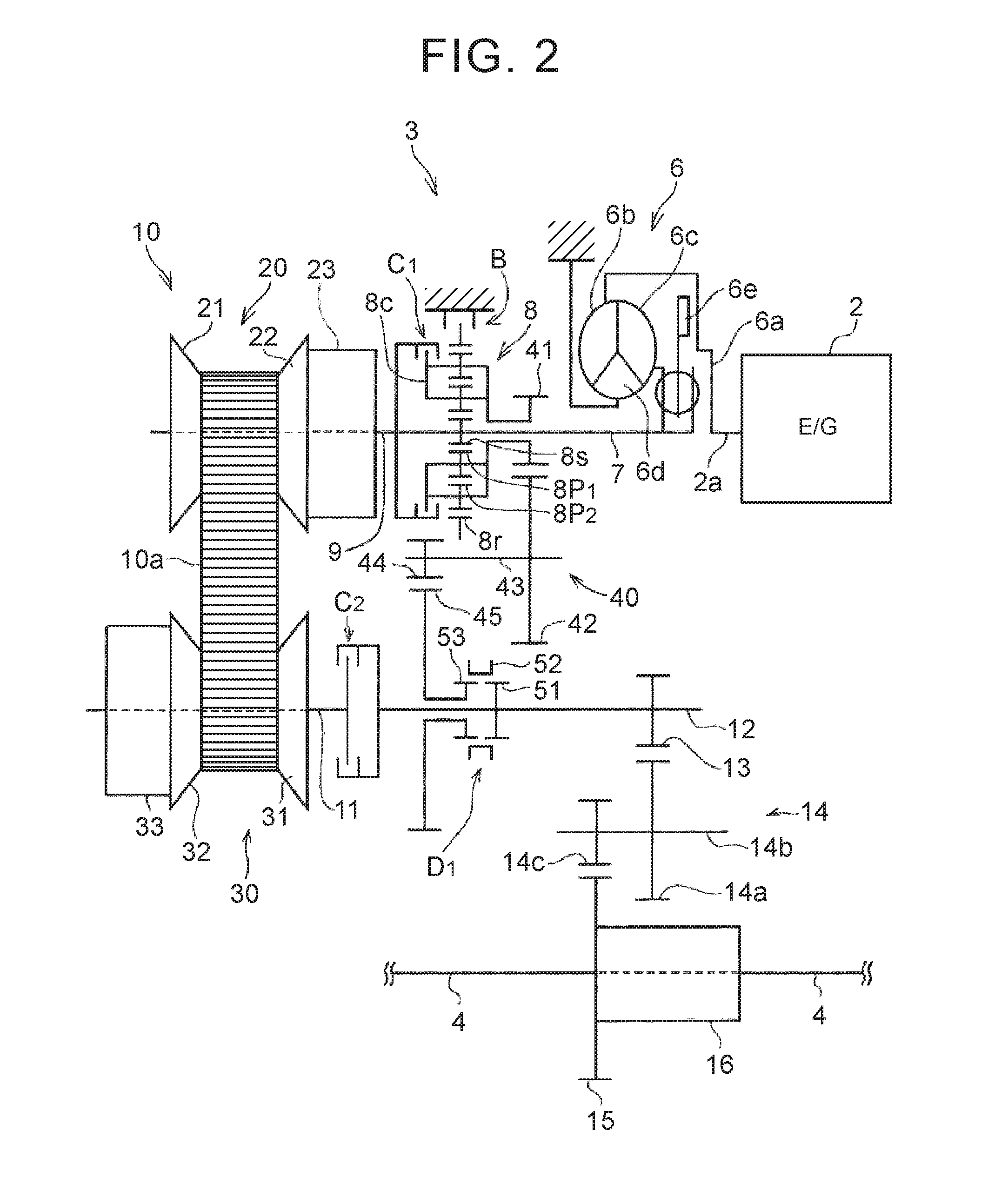
[0047]A description will hereinafter be made on a control device for a vehicle according to the invention on the basis of specified examples. A vehicle as a target of the invention includes plural torque transmission paths that stretch from a power source to drive wheels. Those plural transmission paths include: a transmission path that includes a transmission mechanism capable of setting a fixed transmission gear ratio; and a transmission path that includes a continuously variable transmission capable of continuously changing the transmission gear ratio. Furthermore, the plural transmission paths are arranged in parallel between an input shaft, to which power output by the power source is input, and an output shaft for outputting the power to the drive wheels. Accordingly, the vehicle includes a path switching mechanism for switching the path capable of transmitting torque from one path to the other path. That is, it is configured to allow a vehicle to run in a state where any one ...


PUM


Abstract

A control device for vehicle is includes: transmission mechanism capable of setting fixed transmission gear ratio; continuously variable transmission provided in parallel with transmission mechanism; and path switching mechanism for selectively blocking torque transmission path that includes transmission mechanism and that is configured to dampen vibration. Control device for vehicle includes clutch mechanism wherein continuously variable transmission and transmission mechanism capable of setting constant transmission gear ratio are arranged in parallel between input shaft and output shaft, that selectively connects torque transmission path stretching from internal combustion engine to drive wheels via transmission mechanism in manner capable of transmitting torque, and wherein one clutch and other clutch are arranged in series and other clutch is arranged on relatively downstream side, and is configured to engage either one of one clutch and other clutch in case where torque is transmitted from internal combustion engine to drive wheels via continuously variable transmission.

Description

TECHNICAL FIELD[0001]The invention relates to a control device for a vehicle that includes: plural torque transmission paths that are formed in parallel between an input shaft, to which torque output by a power source is transmitted, and an output shaft for outputting the torque to drive wheels; and a path switching mechanism for switching a path capable of transmitting the torque from one path to the other path.BACKGROUND ART[0002]A configuration of a vehicle that includes: a gear mechanism and a belt-type continuously variable transmission that are provided in parallel; and plural clutch mechanisms for switching a torque transmission path, which stretches from a power source to drive wheels, to a transmission path including a continuously variable transmission or to a transmission path including a transmission mechanism has been described in Japanese Utility Model Application Publication No. 62-45455 (JP 62-45455 U). The configuration described in JP 62-45455 U is configured to be...

Claims


Application Information

Patent Timeline
Patent Type & Authority Applications(United States)
IPC IPC(8): F16H61/70F16H37/08F16H61/02
CPCF16H61/702F16H37/0846F16H61/0204F16H37/022F16H57/0006F16H2037/026F16H59/24F16H59/44F16H59/70F16H2059/366F16H2057/0012
Inventor TOYODA, MITSUHIRONAKADA, HIROFUMIYOSHIDA, MICHIOINOUE, DAISUKEAYABE, ATSUSHIKIMURA, MOTONORIHINO, AKIRAKONDO, HIROKIMATSUO, KENJISHIMAZU, TAKURO
Owner TOYOTA JIDOSHA KK
Why Eureka
Try Eureka