Evaporator with simplified assembly for diphasic loop

a technology of evaporator and assembly, applied in the field of evaporators, can solve the problems of complex production of evaporators placed above each processor, failure or at least regular maintenance, and high cost of evaporators, and achieve the effects of low price, good thermal transfer coefficient, and simple production

Active Publication Date: 2016-05-12
CALYOS
View PDF9 Cites 8 Cited by
  • Summary
  • Abstract
  • Description
  • Claims
  • Application Information

AI Technical Summary

Benefits of technology

[0023]The base plate can include projections projecting inward, where these projections form vapor recovery channels and form spacers for holding the porous mass, such that it is possible to use a very simple porous layer without machining, where the vapor channels result from the shapes of the base plate.
[0024]The porous mass can form a layer of constant thickness parallel to the interface plane P, such that a very low price porous element can be used, which is simply cut to the right length and right width without other preparation.
[0025]The base plate has a rectangular shape and the body has a rectangular shape with four sides forming the lateral portions, such that the base plate can be perfectly suited to the geometry of a processor or CPU onto which it is installed and the body is a part with a geometry that is simple to produce.
[0026]The base plate is made of copper and the body is stainless steel, by means of which the base plate has a very good thermal transfer coefficient and an adequate ductility for the crimping operation. Furthermore, the body has adequate features of durability and compatibility with fluids.
[0027]The body includes fins arranged on the outer surface of the back of the body, such that if gas bubbles were to form in the second liquid chamber, they would re-condense under the cooling effect of the fins.
[0028]The body includes means for attachment to the electronic card, for example in the form of lateral extensions parallel to the plane P, preferably screw holes. In this way the capacity for integration of the evaporator onto an electronics board is improved and the overall cost of the cooling function reduced.

Problems solved by technology

The circulation of such a fluid requires the use of one or several fans or one or several pumps which can be subject to failure or at least require regular maintenance.
Such a system is described in the patent application US2003 / 051859; however, the condenser function still calls for a fan and additionally the evaporator placed above each processor is complex to produce and consequently costly.

Method used


Image

  • Evaporator with simplified assembly for diphasic loop
  • Evaporator with simplified assembly for diphasic loop
  • Evaporator with simplified assembly for diphasic loop

Examples


Embodiment Construction

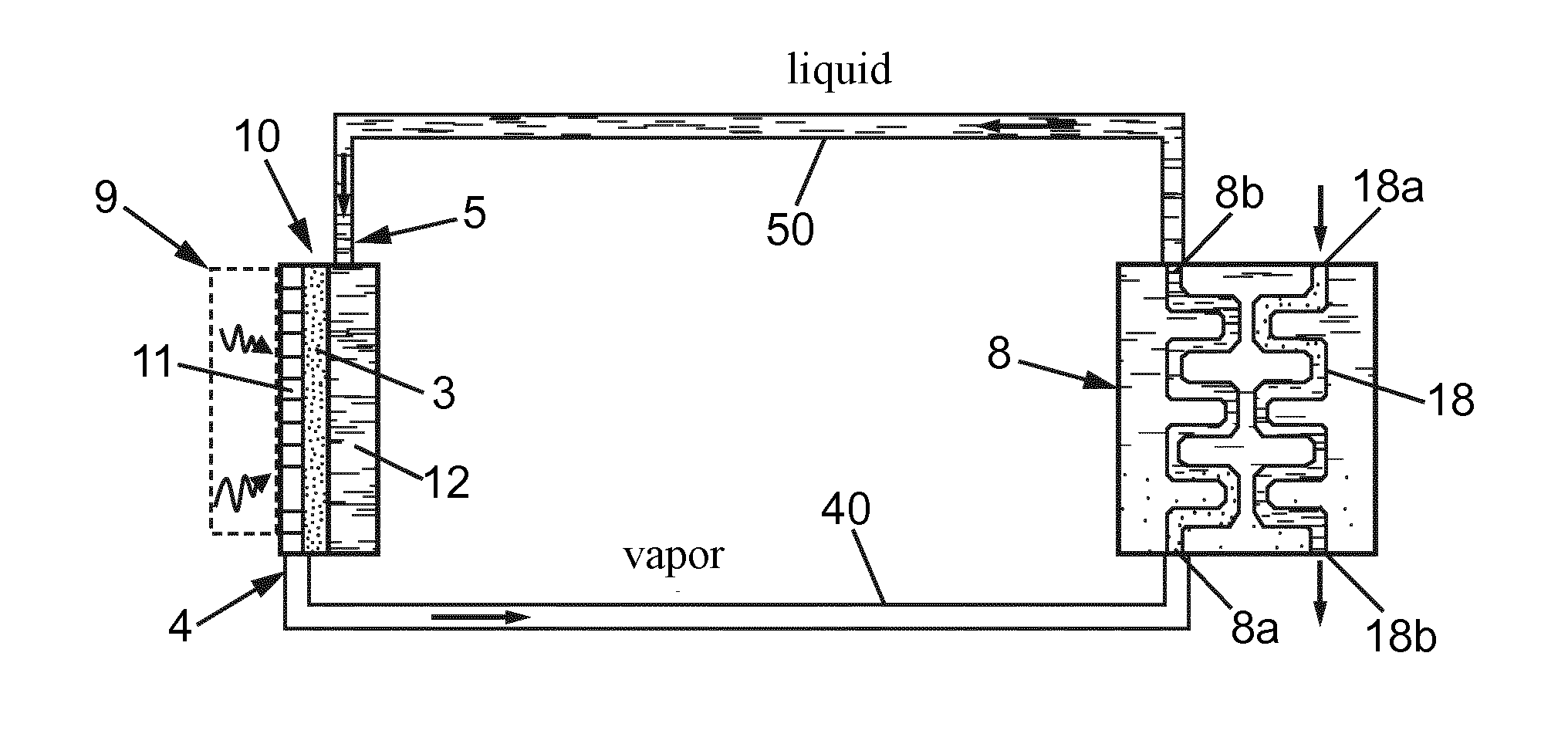
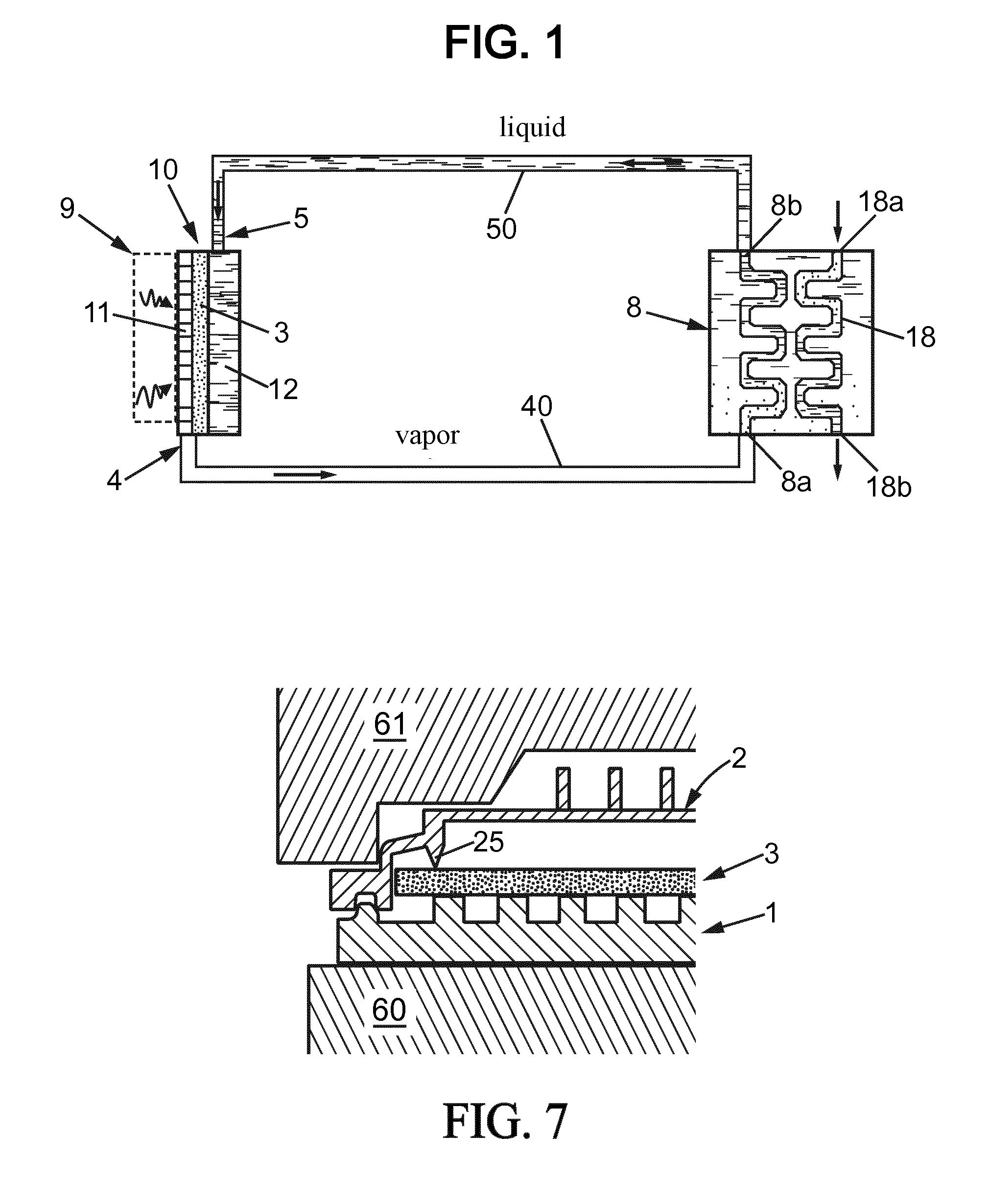
[0045]FIG. 1 shows a sample closed-circuit two-phase loop cooling device which includes an evaporator 10, a condenser module 8, a first fluid pipe 40 referred to as “vapor” connecting the outlet of the evaporator to the inlet of the condenser module and a second fluid conduit 50 referred to as “liquid” connecting the outlet of the condenser module to the inlet of the evaporator.

[0046]The circulation of a two-phase working fluid is assured via the capillary effect prevailing in a porous mass 3 disposed inside the evaporator 10. Said porous mass 3 separates a first chamber 11 in thermal contact with the heat source and generally intended to contain the working fluid in gaseous phase, and a second chamber 12 arranged in the evaporator opposed from the heat source and intended to contain the heating fluid mainly in liquid phase.

[0047]As is well known, the thermal energy supplied near the evaporator transforms the liquid into vapor during which it absorbs an energy equivalent to the late...


PUM

PropertyMeasurementUnit
thicknessaaaaaaaaaa
thicknessaaaaaaaaaa
thicknessaaaaaaaaaa

Abstract

An evaporator for a diphasic heat transfer system with capillary pumping, includes a base plate with a peripheral edge and an outer face for receiving heat receiving calories from a dissipative element, a body with a bottom, side portions and a border adjacent to the peripheral border of the base plate, a porous mass forming a layer with a capillary structure, interposed between the base plate and the bottom, which defines a first gas chamber and a second liquid chamber, the body being assembled on the base plate by crimping, such that there is no need for a gluing, screwing, riveting or welding operation to obtain a tight assembly of the evaporator.

Description

BACKGROUND[0001]1. Technical Field[0002]The present invention relates to evaporators for two-phase thermal transfer systems with capillary pumping.[0003]More specifically, the invention relates to forming and assembling such evaporators, in particular those intended to remove heat produced generally by a dissipative element, in particular, but not exclusively, by any electronic processor or any electronic switching device.[0004]2. Description of the Related Art[0005]The expansion of data exchanged over the Internet network has led to an enormous need for calculating and storage power in servers serving to address the needs of users and in particular these servers are often gathered together in centers called “data centers”.[0006]The cooling needs of the electronic boards making up the servers in these data centers never stops growing because the density of processors in these boards is always higher.[0007]Using air or liquid fluid circulation for cooling the processor on a server bo...

Claims


Application Information

Patent Timeline
Patent Type & Authority Applications(United States)
IPC IPC(8): F28D15/04B23P15/26
CPCF28D15/043F28D15/046B23P15/26F28D15/0266H01L23/427H01L2924/0002H01L2924/00
Inventor DE TROZ, VINCENT
Owner CALYOS
Why Eureka
Try Eureka