
Tire pressure decrease detection apparatus, method, and program

Active Publication Date: 2016-05-12
SUMITOMO RUBBER IND LTD
View PDF12 Cites 5 Cited by
  • Summary
  • Abstract
  • Description
  • Claims
  • Application Information

AI Technical Summary

Benefits of technology

The present invention is a device, method, and program that can detect when the tire pressure is decreasing. It does this by eliminating the influence of regular noise and improving the accuracy of estimating the tire's resonance frequency.

Problems solved by technology

When the pressure is decreased to less than a proper value, operating stability and fuel consumption are deteriorated, so that a tire burst may sometimes be caused.
Although the decrease in the pressure can be detected with high precision, some disadvantages in terms of technique and cost remain, the disadvantages including problems in battery life, maintenance, and fault tolerance in an actual environment.
A major cause of the engine noise is rotation unevenness and torque unevenness of the engine.
Thus, in general, the engine noise appears in left and right wheels of driving wheels in the same phase.

Method used


Image

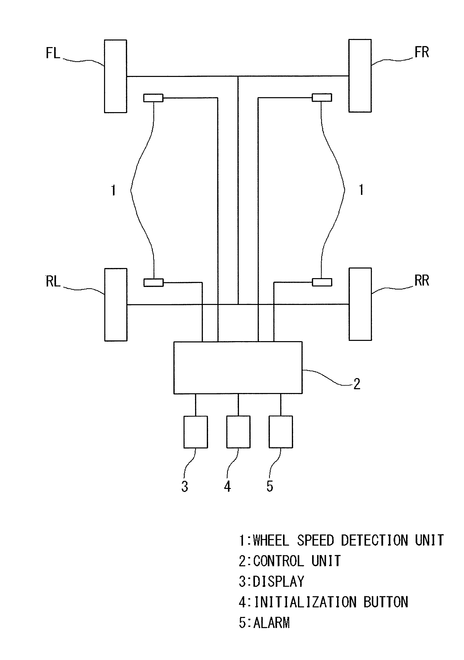
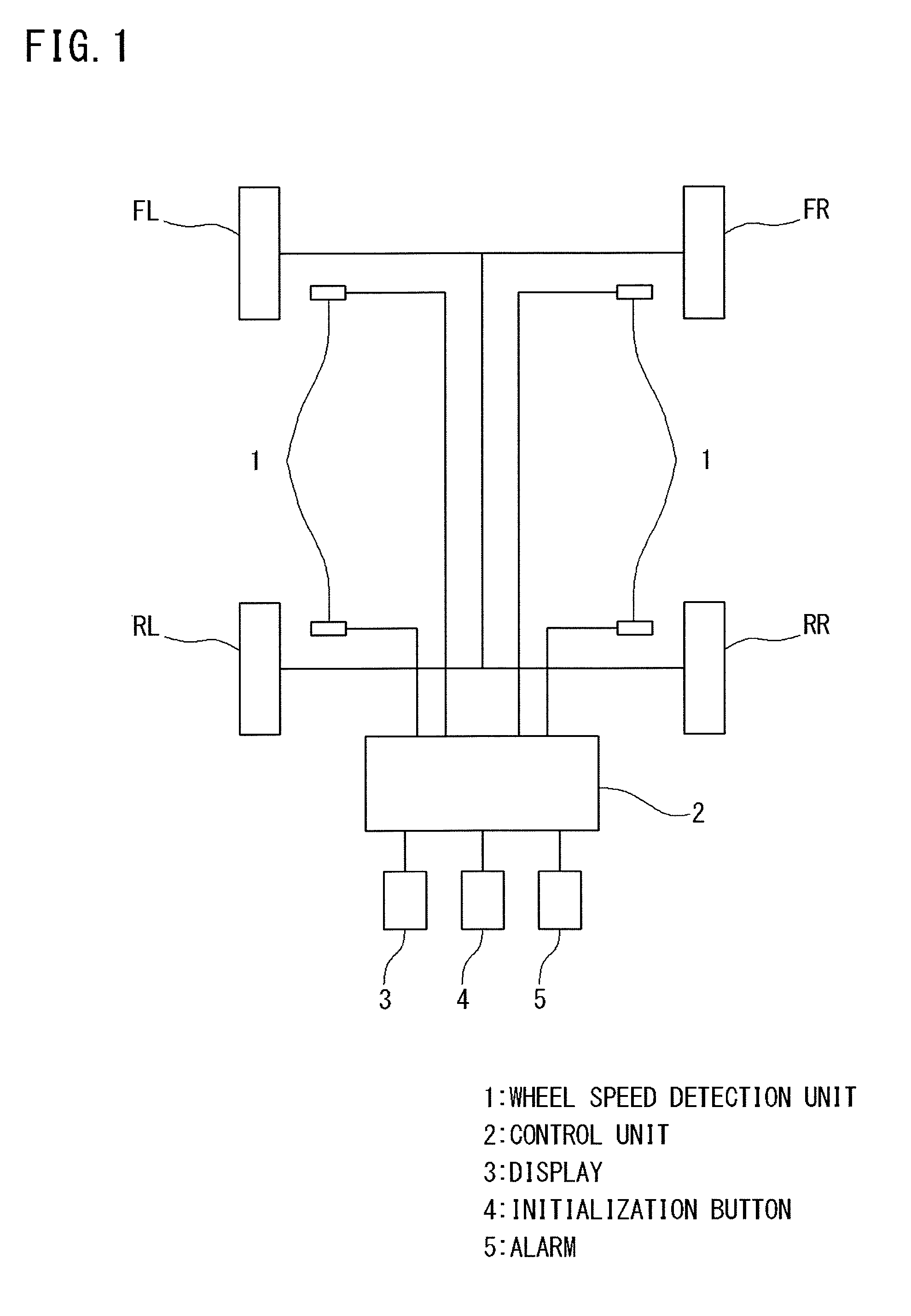
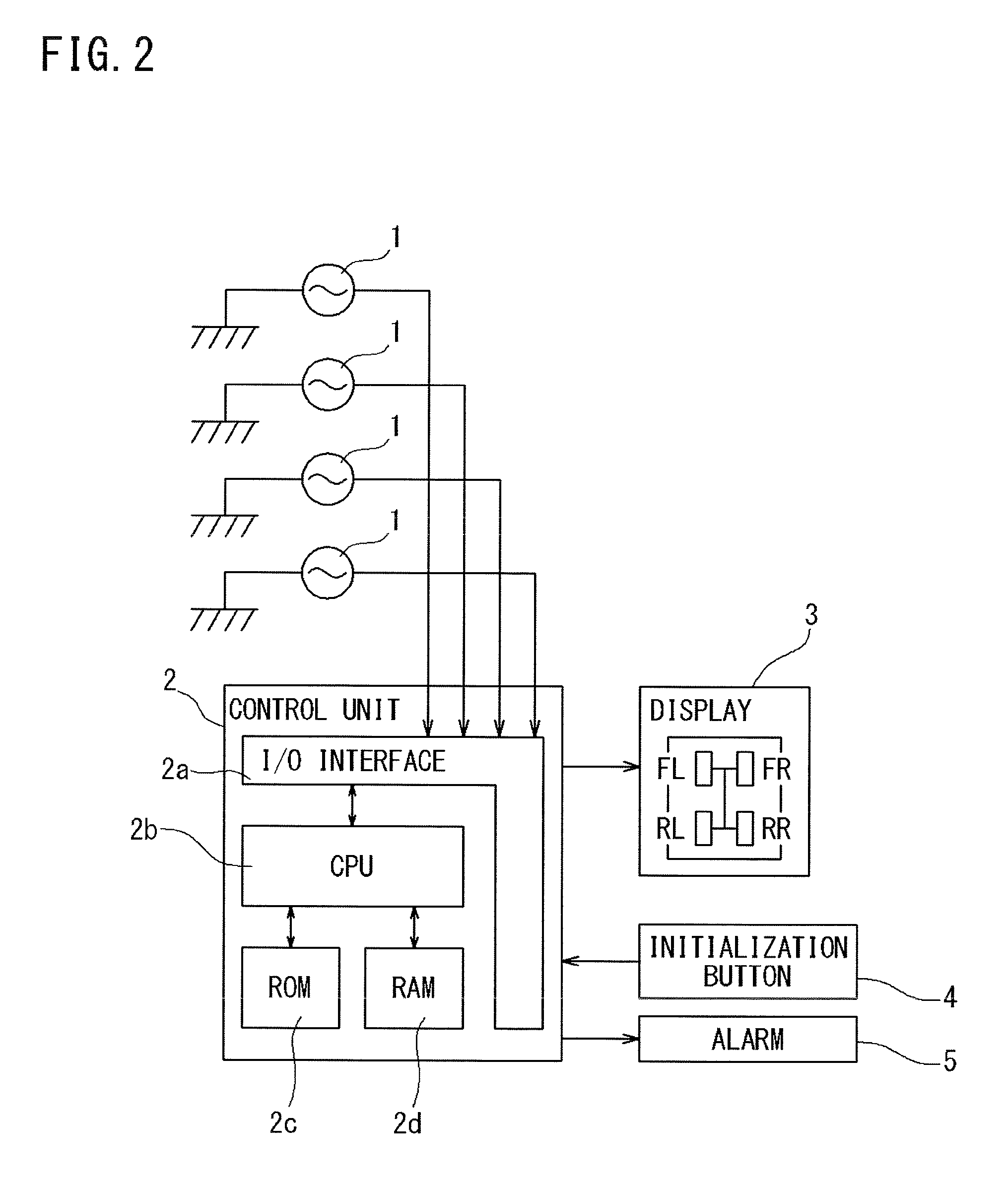
  • Tire pressure decrease detection apparatus, method, and program
  • Tire pressure decrease detection apparatus, method, and program
  • Tire pressure decrease detection apparatus, method, and program

Examples


first embodiment

[0093]In the present embodiment, as the ANC technology, a delayed-x harmonics synthesizer (DXHS) which is an algorithm specialized in removal of a periodic noise such as an engine noise caused by an explosion of the engine is used.

[0094]A frequency of the engine noise can be calculated from the engine rotation number serving as engine rotation number information and the cylinder number. In the present embodiment, the noise removal unit functions in a case where the calculated frequency is within a ranged from 25 to 65 Hz. Since a tire torsional resonance in the vicinity of 40 Hz is intended in the RFM method which is a premise of the detection apparatus or the method according to the present embodiment, an influence of a noise at a frequency less than 25 Hz or exceeding 65 Hz is not easily exerted. Thus, there is no need for removing such a noise.

[0095]In terms of calculation precision, calculation speed, and easiness of specifying of a resonance peak, the ANC desirably functions at...

second embodiment

[0100]In the present embodiment, the ANC technology is an FIR type adaptive digital filter using a past signal of the wheel speed signal or a wheel acceleration signal serving as an object to be controlled as a reference signal, and an LMS algorithm as an adaptive algorithm. That is, in the present embodiment, the object-to-be-controlled signal and the reference signal are the same as each other.

[0101]Firstly, for reference, a case where the object-to-be-controlled signal (=d(n)) and the reference signal (=noise source x(n)) are different from each other will be described.

[0102]FIG. 4 is a chart showing a system flow in a case where the object-to-be-controlled signal (=d(n)) and the reference signal (=noise source x(n)) are different from each other. In this case, the control signal (=y(n)) and an error signal (=e(n)) are expressed by the following expressions (2) and (3), and a filter coefficient vector (=h(k, n)) is updated in accordance with the following expression (4).

y(n)=∑k=0...

example 1

[0129]A small FF (front-engine, front-drive) vehicle of a three-cylinder engine traveled in a test course (round circuit) and wheel speed of two front wheels was measured. The FF vehicle is a manual transmission vehicle, and data obtained when the vehicle traveled with a gearshift position of “fifth” at 60 kph was used. An engine noise in the vicinity of 39 Hz was canceled with using the DXHS according to the first embodiment. A result is shown in FIGS. 15A and 15B. In FIGS. 15A and 15B, a broken line indicates a gain before control, and a solid line indicates a gain after control.


PUM


Abstract

A tire pressure decrease detection apparatus comprising a rotation speed information detection unit for detecting rotation speed information of wheels of a vehicle, a resonance frequency estimate unit for time-series estimating a torsional resonance frequency of the rotation speed information from the rotation speed information obtained by the rotation speed information detection unit, and a judgment unit for judging a decrease in pressure of tires installed in the wheels based on the estimated torsional resonance frequency. The resonance frequency estimate unit includes a noise removal unit for removing a noise superimposed on a wheel speed signal serving as the rotation speed information for each of the wheels with using an active noise control technology.

Description

TECHNICAL FIELD[0001]The present invention relates to a tire pressure decrease detection apparatus, a method, and a program. Further in detail, the present invention relates to a tire pressure decrease detection apparatus, a method, and a program for detecting a decrease in pressure of tires based on a torsional resonance frequency of the tires of a traveling vehicle.BACKGROUND ART[0002]One of factors for letting an automobile safely travel includes pressure of a tire. When the pressure is decreased to less than a proper value, operating stability and fuel consumption are deteriorated, so that a tire burst may sometimes be caused. Therefore, a tire pressure monitoring system (TPMS) for detecting a decrease in tire pressure and issuing an alarm so as to urge a driver to take a proper action is an important technique from a view of protecting an environment and ensuring safety of the driver.[0003]The conventional monitoring system can be classified into two types including a direct de...

Claims


Application Information

Patent Timeline
IPC IPC(8): G01L17/00G01P3/00
CPCG01P3/00G01L17/00B60C23/00B60C23/061B60C23/062
Inventor YANASE, MINAO
Owner SUMITOMO RUBBER IND LTD
Learn More