Multi-layer packaging scheme for implant electronics

a technology for implant electronics and packaging schemes, applied in microstructural devices, surgery, therapy, etc., can solve the problems of harsh and corrosive body fluids for devices, and achieve the effect of preserving flexibility and low water vapor transmission ra

Active Publication Date: 2016-05-12
CALIFORNIA INST OF TECH
View PDF3 Cites 4 Cited by
  • Summary
  • Abstract
  • Description
  • Claims
  • Application Information

AI Technical Summary

Benefits of technology

[0004]The present invention provides a new protection scheme of a thin-film-(metal)-thin-film sandwich architecture for a corrosion barrier. The sandwich architecture is a flexible composite. Advantageously, the corrosion barrier has a low water vapor transmission rate (WVTR) and preserves flexibility, which are important features for devices such as retinal implants.

Problems solved by technology

These devices, however, will have to endure harsh and corrosive body fluids (see, W. Li et al., ECS Transactions, vol.

Method used


Image

  • Multi-layer packaging scheme for implant electronics
  • Multi-layer packaging scheme for implant electronics
  • Multi-layer packaging scheme for implant electronics

Examples


example 1

Shows the Flexibility of the Sandwich Corrosion Barrier

[0073]Water vapor permeation is one of the main causes of failure in parylene devices when implanted. In order to create better protection, bio-compatible metals, such as titanium, gold, platinum and combinations thereof are chosen as the metals in parylene-metal-parylene flexible composite protection layers to protect devices from water vapor corrosion. FIG. 9A shows that even after sandwich layer protection, the device is highly flexible. FIG. 9B shows that the device becomes inflexible after coating with thick silicone.

example 2

Shows a Comparison of Various Protection Schemes Using MTTF

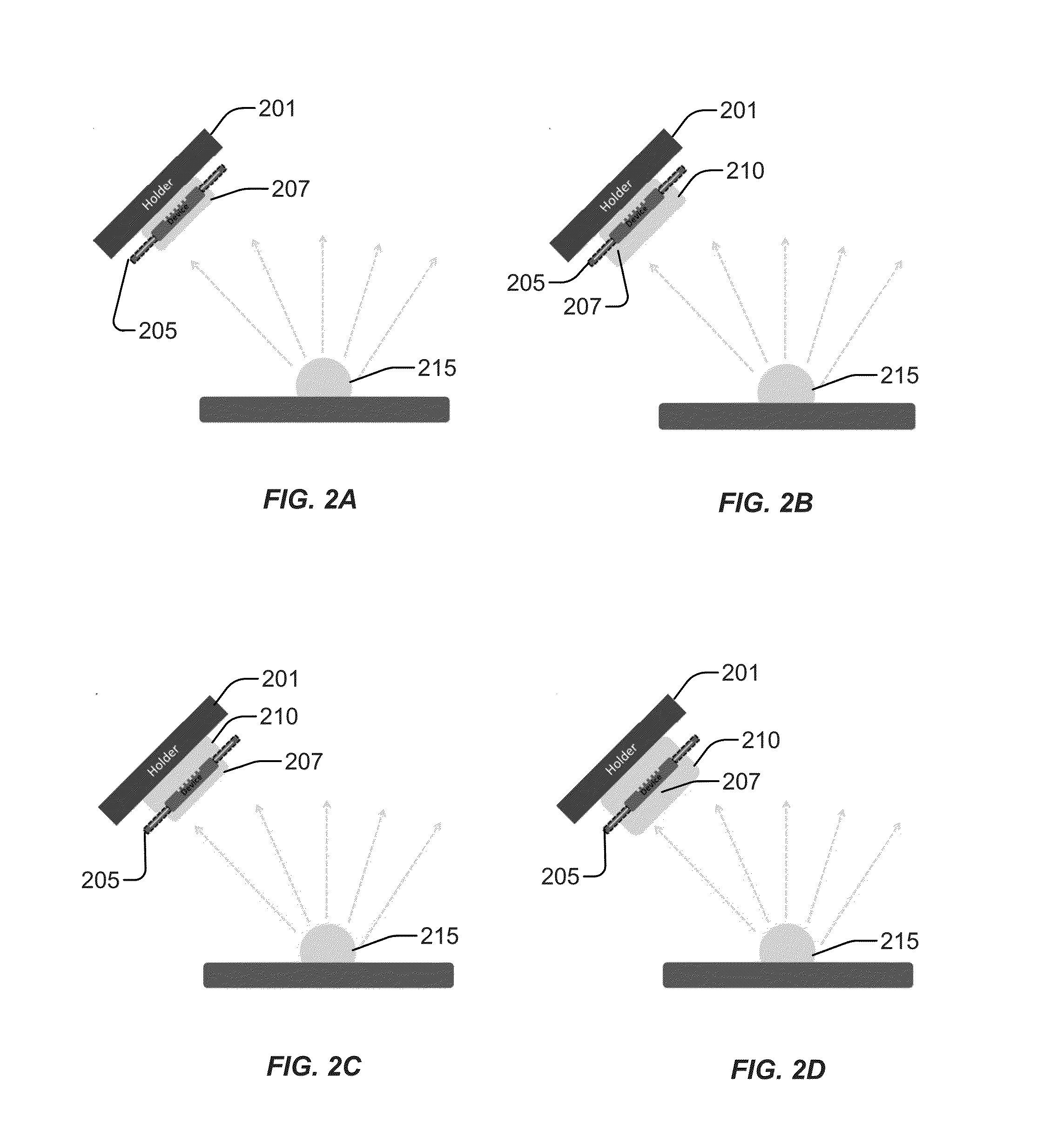
[0074]Water vapor transmission rates (WVTR) of a 0.5 μm metal with high flexibility is lower than that of a 5 mm-thick silicone by a theoretical calculation. Advantageously, the device of the present invention is highly flexible even after sandwich layer protection. However, extra care needs to be taken of the metal coating. Samples need to be fixed at around 45° to the metal source and both sides need to be coated in turn to create continuous metal film to ensure good encapsulation. In addition, the holder must be constantly rotated to create a uniform metal film.

[0075]As is shown in FIG. 10 A-D, 4 devices were compared. In FIG. 10A, no protection was used. In FIG. 10B, a 40 μm parylene-C layer was used as protection. FIG. 10C shows a parylene-C coated bio-compatible silicone. FIG. 10D is the inventive parylene-C-metal-parylene C architecture. Samples are then tested under active soaking conditions.

[0076]All tests are perfo...

example 3

Shows a Device that Can be Protected Using the Present Protection Scheme

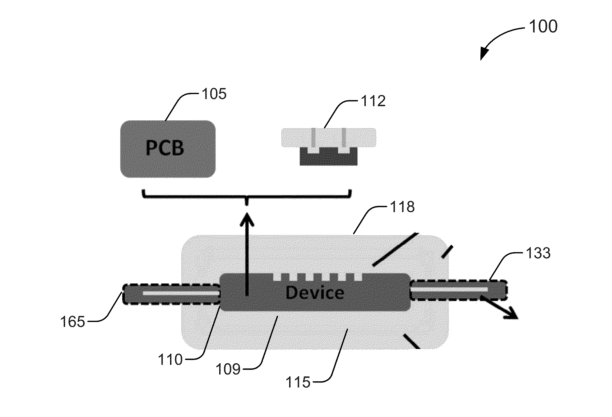
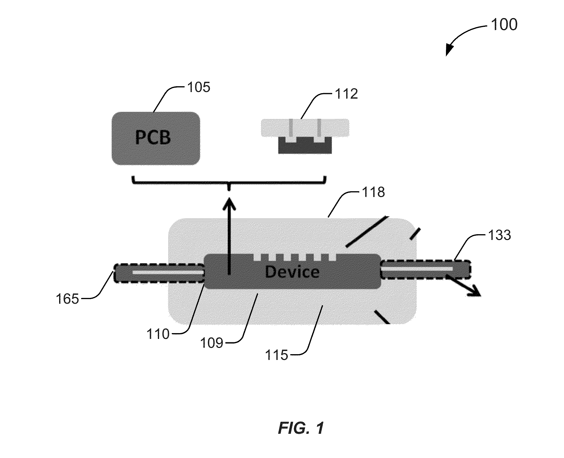
[0087]FIGS. 12A-C show one embodiment of a device suitable to be micropackaged using the present invention. In this instance, the present invention provides a retinal implant. In certain aspects, the present invention provides a wireless retinal implant 1200 having a high density multi-channel IC chip, discrete components (caps, inductors, oscillators, and the like), and coils (power and data coils) packaged with a high-density stimulating electrode array. FIGS. 12A-B show the schematic of a retinal implant chip 1205a,b (in A and B) having discrete components 1230a,b and in electrical communication 1207a,b with output electronics 1210a,b. The chip also has a data coil 1220a,b and a power coil 1222a,b.

[0088]As shown in FIG. 12C, the wireless retinal prosthesis is implanted in a mammalian eye 1240. The chip 1205 and associated components are implanted in the front of the eye (proximal part of the eye) with a cabl...


PUM


Abstract

The present invention provides a micropackaged device comprising: a substrate for securing a device with a corrosion barrier affixed to the substrate, wherein the corrosion barrier comprises a first thin-film layer, a metal film coating the thin-film layer and a second thin-film layer to provide a sandwich layer; and optionally at least one feedthrough disposed in the substrate to permit at least one input and or at least one output line into the micropackaged device, wherein the micropackaged device is encapsulated by the corrosion barrier. Methods of producing the micropackaged device are also disclosed.

Description

CROSS-REFERENCES TO RELATED APPLICATIONS[0001]The present application is a continuation of PCT / US2014 / 055379, filed Sep. 12, 2014, which application claims priority to U.S. Provisional Application No. 61 / 878,983, filed Sep. 17, 2013, the contents of which is hereby incorporated by reference in its entirety for all purposes.BACKGROUND OF THE INVENTION[0002]MEMS technology has been used more and more in biomedical applications for neural prosthetic implantation (see, M. M. Mojarradi et al., IEEE Transactions on Neural Systems and Rehabilitation Engineering, vol. 11, pp. 38-42 (2003); C. Pang et al. “A new multi-site probe array with monolithically integrated parylene flexible cable for neural prostheses” in Digest Tech. Papers EMBS '05 Conference, Jan. 12-18, 2006, pp. 7114-7117). These devices, however, will have to endure harsh and corrosive body fluids (see, W. Li et al., ECS Transactions, vol. 11, pp. 1-6 (2008)). Therefore, biostable and hermetic-like packaging is needed to prote...

Claims


Application Information

Patent Timeline
Patent Type & Authority Applications(United States)
IPC IPC(8): H01L23/31A61B50/30H01L21/56
CPCH01L23/3135A61B50/30H01L21/56B81C1/00H01L23/564H01L2924/0002A61N1/3758A61N1/36046A61N1/37211H01L2924/00A61F2/14
Inventor TAI, YU-CHONGCHANG, HAN-CHIEH
Owner CALIFORNIA INST OF TECH
Why Eureka
Try Eureka