Additive manufacturing apparatus and method

a manufacturing apparatus and additive technology, applied in the field of additive manufacturing apparatus and method, can solve the problems of affecting the accuracy with which the object is built, the amount of debris may not be carried by the gas flow, and the object being built inaccurately, so as to facilitate the desired gas circulation and the effect of greater freedom

Active Publication Date: 2016-05-19
RENISHAW PLC
View PDF0 Cites 99 Cited by
  • Summary
  • Abstract
  • Description
  • Claims
  • Application Information

AI Technical Summary

Problems solved by technology

A problem with the gas flow generated by such arrangements is that the gas flow may not be sufficient to carry all debris to the exhaust vents and some of the debris may be blown onto powder that has yet to be scanned.
This can result in the object being built inaccurately.
This projection can cause damage to the wiper blade, which in turn, can result in subsequent layers of powder having a ridge at a location corresponding to the area of the wiper blade that is damaged.
These ridges are created in each layer for the rest of the build, affecting the accuracy with which the object is built.
However, with the apparatus described above, it may be necessary to compromise between optimum scan direction based on gas flow direction and the desire to change the scan direction for different layers and / or different portions of a layer.

Method used


Image

  • Additive manufacturing apparatus and method
  • Additive manufacturing apparatus and method
  • Additive manufacturing apparatus and method

Examples


Embodiment Construction

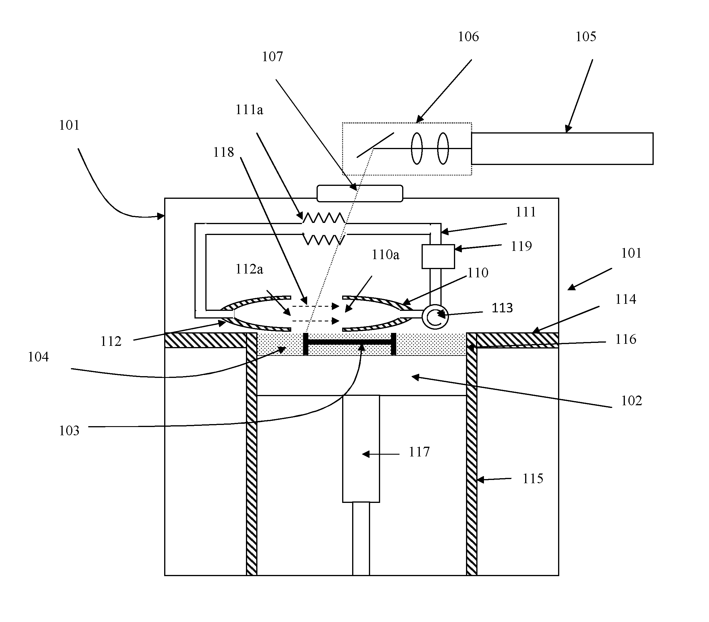
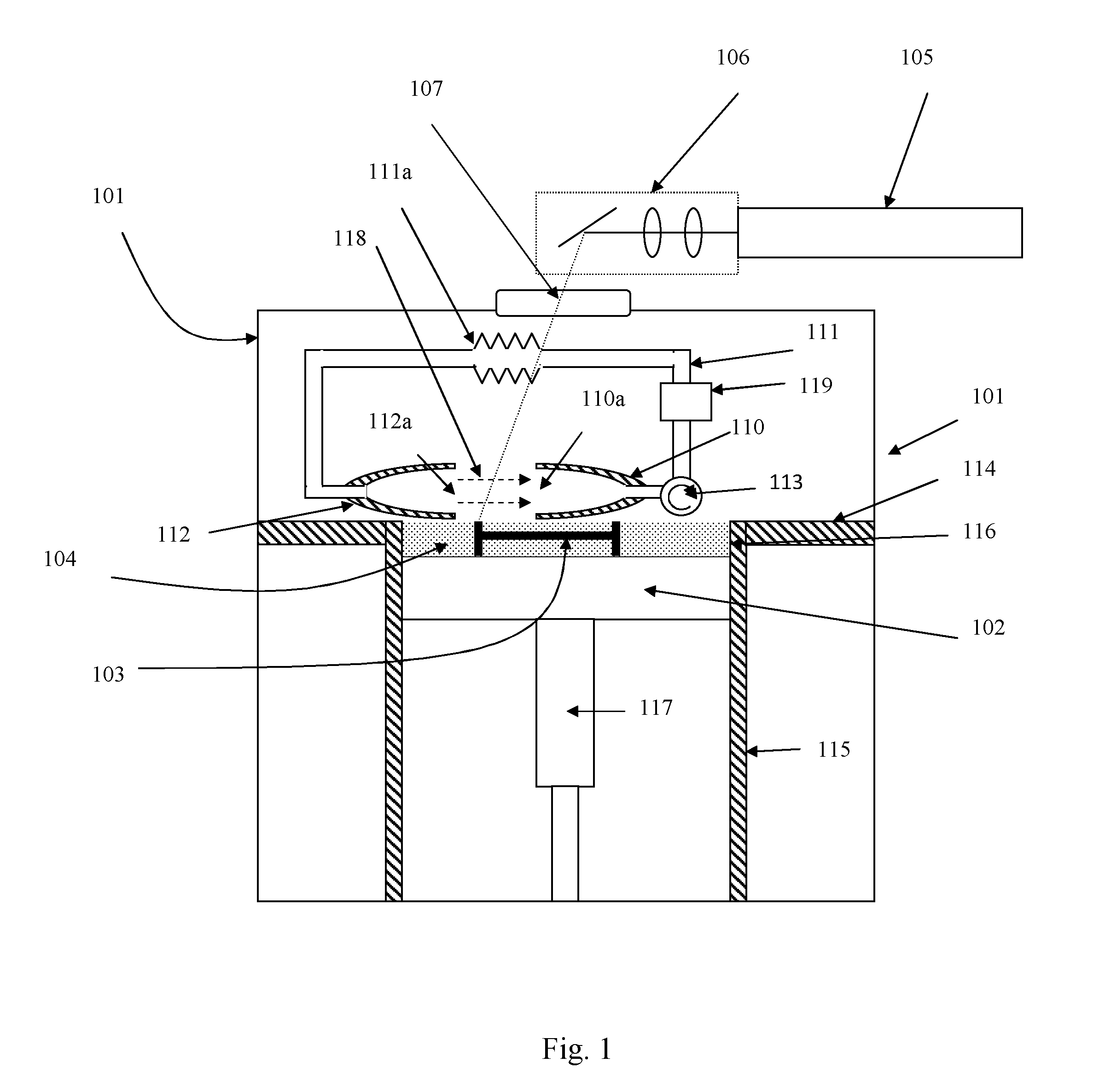
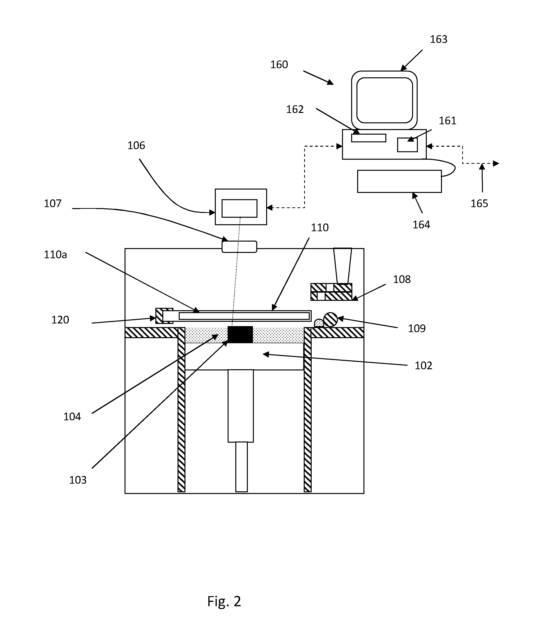
[0064]Referring to FIGS. 1 and 2, a laser solidification apparatus according to an embodiment of the invention comprises a build chamber 101 having therein partitions 114, 115 that define a build volume 116 and a surface onto which powder can be deposited. A build platform 102 defines a working area in which an object 103 is built by selective laser melting powder 104. The platform 102 can be lowered within the build volume 116 using mechanism 117 as successive layers of the object 103 are formed. A build volume available is defined by the extent to which the build platform 102 can be lowered into the build volume 116. Layers of powder 104 are formed as the object 103 is built by dispensing apparatus 108 and a wiper 109. For example, the dispensing apparatus 109 may be apparatus as described in WO2010 / 007396. A laser module 105 generates a laser for melting the powder 104, the laser directed onto the powder bed 104 as required by optical module 106 under the control of a computer 16...


PUM

PropertyMeasurementUnit
distanceaaaaaaaaaa
widthaaaaaaaaaa
areaaaaaaaaaaa

Abstract

An additive manufacturing apparatus for building objects by layerwise consolidation of material. The apparatus includes a build chamber containing a working area, a high energy beam for consolidating material deposited in the working area in layers and a flow device for generating a gas flow across at least a part of the working area from a gas inlet to a gas outlet. The gas inlet and gas outlet are arranged to be movable within the build chamber.

Description

SUMMARY OF INVENTION[0001]This invention concerns an additive manufacturing apparatus and method. The invention has particular, but not exclusive, application to providing gas flow across a powder bed in a laser solidification apparatus.BACKGROUND[0002]Additive manufacturing or rapid prototyping methods for producing objects comprise layer-by-layer solidification of a material, such as a metal powder material, using a high energy beam, such as a laser beam or electron beam. A powder layer is deposited on a powder bed in a build chamber and a laser beam is scanned across portions of the powder layer that correspond to a cross-section of the object being constructed. The laser beam melts or sinters the powder to form a solidified layer. After selective solidification of a layer, the powder bed is lowered by a thickness of the newly solidified layer and a further layer of powder is spread over the surface and solidified, as required.[0003]During the melting or sintering process, debris...

Claims


Application Information

Patent Timeline
Patent Type & Authority Applications(United States)
IPC IPC(8): B22F3/105
CPCB22F3/1055B22F2003/1057B22F2003/1059B33Y40/00B33Y30/00B33Y50/02B33Y10/00B29C64/153B22F2203/00B22F2201/00B22F2999/00B29C64/371Y02P10/25B08B15/04B22F12/67B22F10/366B22F10/77B22F10/322B22F10/28B22F12/70B22F12/90
Inventor MCMURTRY, DAVID ROBERTSDIMTER, MARCMAYER, RALPH
Owner RENISHAW PLC
Why Eureka
Try Eureka