Impact Reinforced Composite Spring Seat for a Shock Absorber

a composite spring seat and shock absorber technology, applied in the direction of shock absorbers, wound springs, transportation and packaging, etc., can solve the problems of limited creep, failure to achieve successful attempts, and the spring seat can become brittle, crack or shatter, etc., to enhance the impact resistance of the lower spring seat, avoid dangerous and hazardous conditions, and improve the impact resistance

Active Publication Date: 2016-05-19
TENNECO AUTOMOTIVE OPERATING CO INC
View PDF10 Cites 12 Cited by
  • Summary
  • Abstract
  • Description
  • Claims
  • Application Information

AI Technical Summary

Benefits of technology

[0011]The subject invention provides a strut assembly that comprises a top mount assembly, a shock absorber, and an upper spring seat supported by the top mount and a lower spring seat supported by the shock absorber. The upper and the lower spring seats are spaced apart from one another and a coil spring is disposed between the upper and the lower spring seats. The lower spring seat comprises an annular disc defining an opening. The lower spring seat is formed of a composite material and includes at least one reinforcing element disposed between an upper surface and a lower surface of the lower spring seat for improving impact resistance thereof.
[0012]The present invention overcomes the disadvantages in the related art. Specifically,

Problems solved by technology

When the spring seats are formed of composite materials, it is a challenge to have a sufficiently strong and stiff design with very limited creep.
Attempts have been made to increase the thickness of the composite materials to give improved strength, but these attempts have not been successful due to the cost of the additional material.
Further, the performance of the composite spring seats has to be able to withstand significant temperature differences, such as extreme heat and extreme cold.
When the composite spring seats are exposed

Method used


Image

  • Impact Reinforced Composite Spring Seat for a Shock Absorber
  • Impact Reinforced Composite Spring Seat for a Shock Absorber
  • Impact Reinforced Composite Spring Seat for a Shock Absorber

Examples


Embodiment Construction

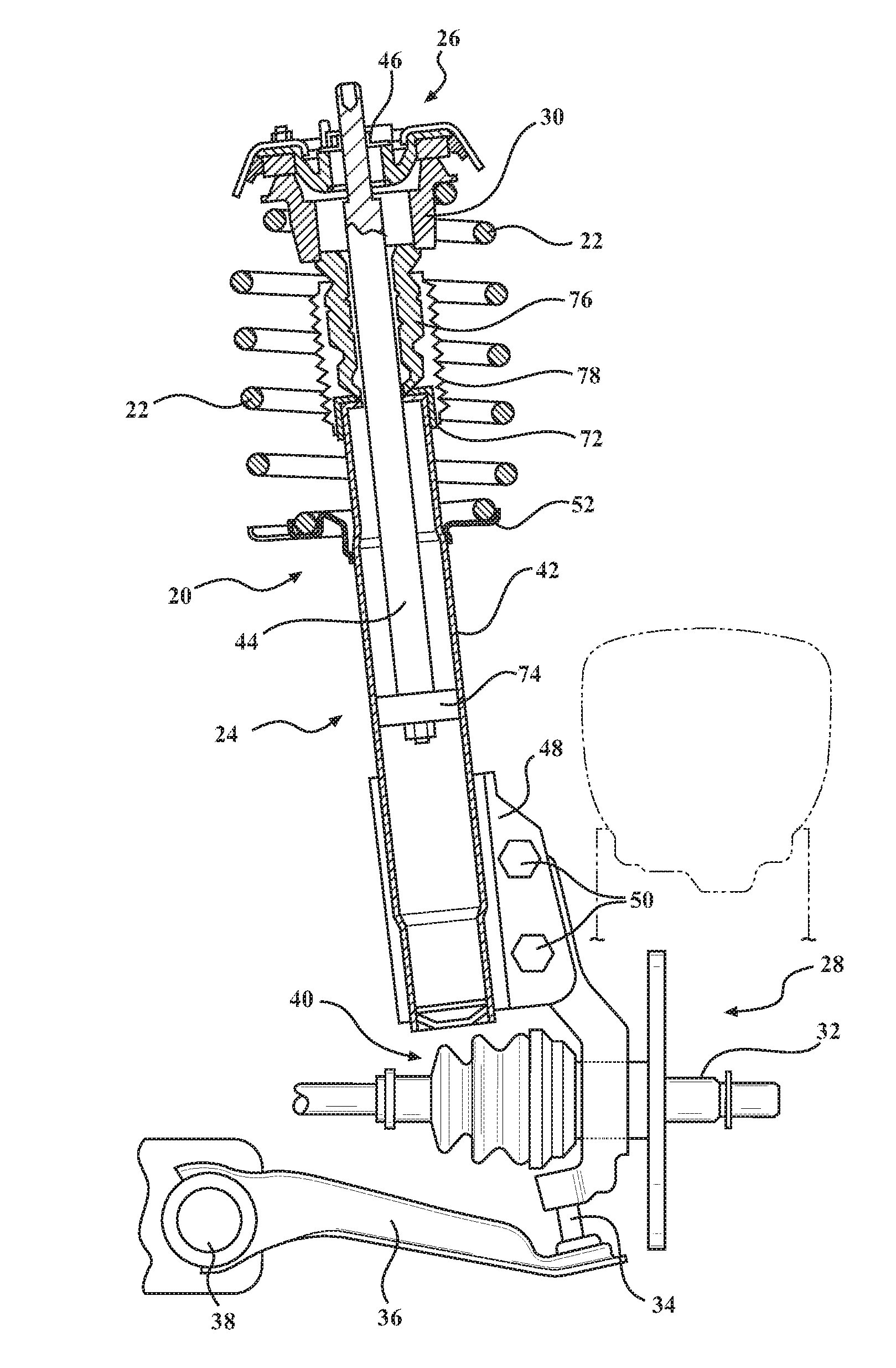
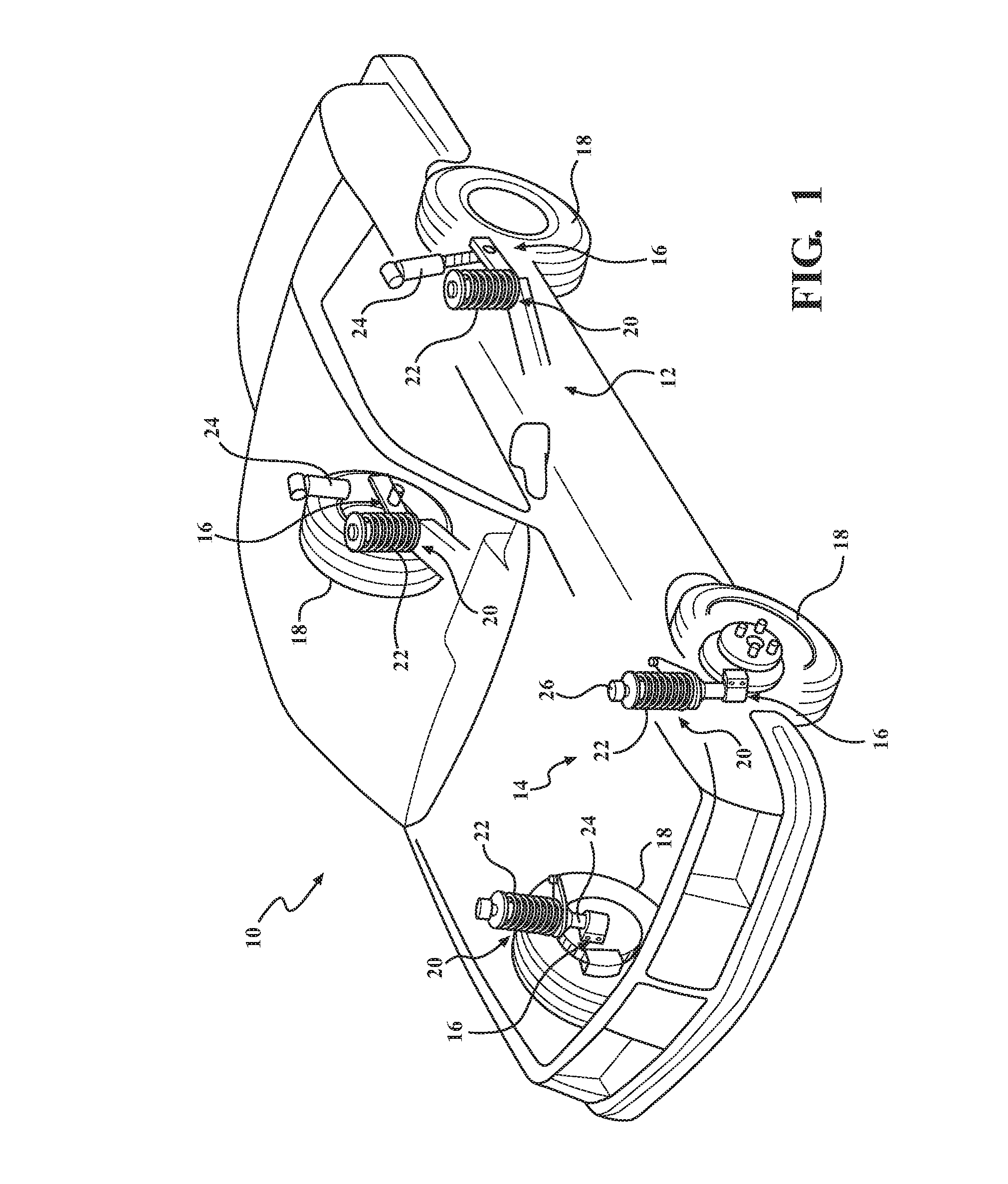
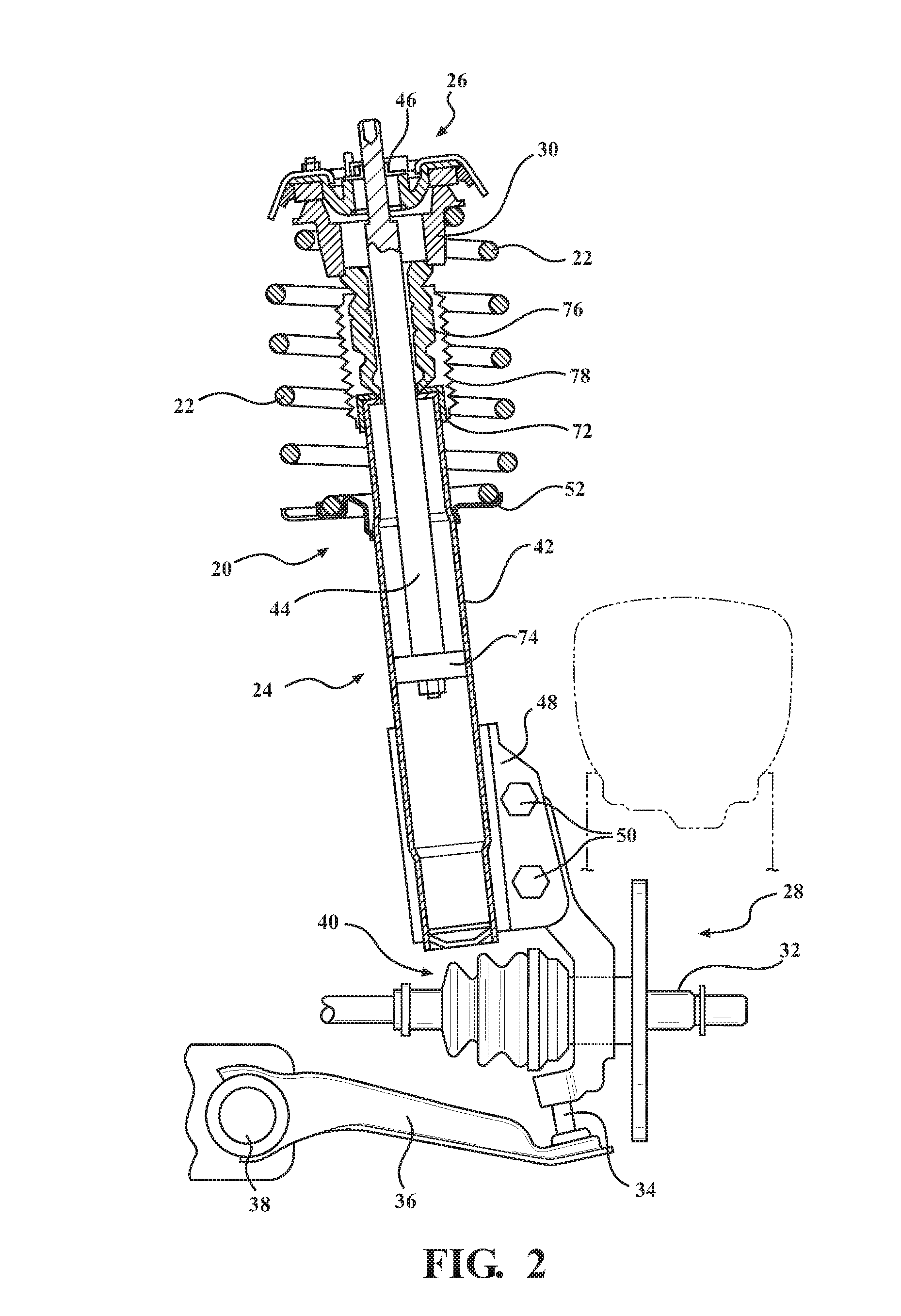
[0023]With reference to the Figures, where like numerals are used to designate like structures throughout the several views, a portion of a conventional vehicle is illustrated at 10 in FIG. 1. The vehicle 10 includes a body 12 operatively attached to a suspension system 14 defined by four corner assemblies 16. The corner assemblies 16 are each assigned to a rotatably supported wheel 18 and are used to control the relative motion between the vehicle body 12 and wheel operation. The corner assemblies 16 each typically include strut assemblies 20 that include a spring 22 to help absorb impacts and a shock absorber 24 to help control motion of the spring 22 by damping movement between the wheel 18 and vehicle body 12.

[0024]As shown in FIG. 1, the springs 22 are compression springs and can be either concentrically aligned around the shock absorber 24, or spaced from the shock absorber 24. Thus, those having ordinary skill in the art will appreciate that the shock absorber 24 of the prese...


PUM


Abstract

A strut assembly including a spring to help absorb impacts and a shock absorber to help control motion of the spring is disclosed. The shock absorber includes a base assembly and is mounted between a top mount assembly and a knuckle. The top mount assembly mounts to the body of the vehicle and helps support the spring. An upper spring seat is adjacent the top mount assembly and receives one end of the spring. A lower spring seat formed of a composite material is supported by the base assembly and is adapted to support another end of the spring. The lower spring seat includes at least one reinforcing element having a plurality of reinforcing cords disposed between an upper surface and a lower surface for improving impact resistance thereof.

Description

RELATED APPLICATIONS[0001]This application is a continuation-in-part application of PCT Patent Application PCT / EP2014 / 073627, filed on Nov. 4, 2014, and this application claims priority to U.S. Provisional Patent Application No. 62 / 107,647, filed on Jan. 26, 2015, both of which are hereby incorporated by reference.BACKGROUND OF THE INVENTION[0002]1. Field of the Invention[0003]The present invention relates generally to composite spring seats for shock absorbers, and more specifically, to impact reinforced composite spring seats for shock absorbers.[0004]2. Description of the Related Art[0005]Strut-type suspension systems are well known in the motor vehicle industry. A telescopic strut assembly normally incorporating a hydraulic damper is used as one of the locating members for a wheel of a motor vehicle. The most common form of a strut-type suspension is the MacPherson strut suspension system. The MacPherson strut assembly includes a coil spring located concentrically around the tel...

Claims


Application Information

Patent Timeline
IPC IPC(8): B60G15/06B60G15/07
CPCB60G15/063B60G15/062B60G2204/1242B60G2202/312B60G15/07B60G2204/12422B60G2206/013B60G2206/7101F16F1/12
Inventor WILKIN, JULIEN
Owner TENNECO AUTOMOTIVE OPERATING CO INC
Why Eureka
Try Eureka