Compact sensor for measuring turbidity or fluorescence in a fluid sample

a fluid sample and sensor technology, applied in the field of water quality instruments, can solve the problems of sacrificing sensor performance, affecting the accuracy of measurement results, so as to achieve the effect of reducing the frequency of calibration, sacrificing sensor performance, and inability to reliably position desired optical components

Active Publication Date: 2016-05-19
INSITU INC
View PDF9 Cites 19 Cited by
  • Summary
  • Abstract
  • Description
  • Claims
  • Application Information

AI Technical Summary

Benefits of technology

[0009]The disadvantages associated with the geometry and inability to reliably position desired optical components without sacrificing sensor performance is addressed herein by the use of a specially configured sensor having a sensing surface that is a portion of a circle, also referred generally herein as a “pie” type geometry. This geometry allows for a larger linear dimension inside the sensor to accommodate additional optics and electro-optics for performing real-time closed loop type corrections and compensation for variation in optical output that simply are not possible with conventional lay-outs. The sensors provided herein address and overcome these limitations by specially configuring integrated reference detector and beam splitter in a compact in-situ instrument for long term deployment, lower frequency of calibration and accurate monitoring independent of time, temperature and other environmental variables.

Problems solved by technology

The disadvantage of such sensors arises from the light source, such as a light emitting diode (LED), whose brightness changes with temperature.
Such change in optical output with change in temperature can show up as a false or erroneous change in the readings of the sensor.
This is time consuming, is not always accurate, and can be very non-linear, as LED optical output is generally non-linear with temperature.
Devices that measure at two optical path lengths generally require much larger sensor geometries unsuitable for sub-two inch sonde or multi-parameter sondes comprising multiple probes.
The designs that work over a shorter path length to optimize range generally suffer from increased noise because of the much smaller excitation / detection volume due to noise statistics related to exciting and detecting in a smaller scattering volume.
One reason for this is that the in-situ sensors typically have a limited amount of space in them and simply cannot accommodate the added detector in a reliable manner without unduly sacrificing dynamic range and / or signal-to-noise ratio.
When the LED output changes however, including for non-temperature related reasons, this method does not work.
There are “closed loop” systems, but they are typically bulky on-line monitoring type analyzers, not suited for in-situ monitoring applications.
The round geometry of the sensors greatly limits the optics that can be squeezed into such a sensor.

Method used


Image

  • Compact sensor for measuring turbidity or fluorescence in a fluid sample
  • Compact sensor for measuring turbidity or fluorescence in a fluid sample
  • Compact sensor for measuring turbidity or fluorescence in a fluid sample

Examples


example 1

Sensor Housing Configuration and Form Factors

[0080]The sensors may generally be described as “pie shaped”, and can have an interlocking feature that holds the sensors together. The interlocking feature can be a tongue and grove design that holds all the sensors to the center support that is operably connected to the wiper. This has a number of benefits, including enhancing impact resistance as the interlocking protects the sensors during a drop or impact in situations where the sensor guard is not installed. It also holds the sensors tightly together and makes sensor guard installation easier. Without the interlocking feature the sensors tend to splay out and have to be pushed together to install the tightly fitting sensor guard.

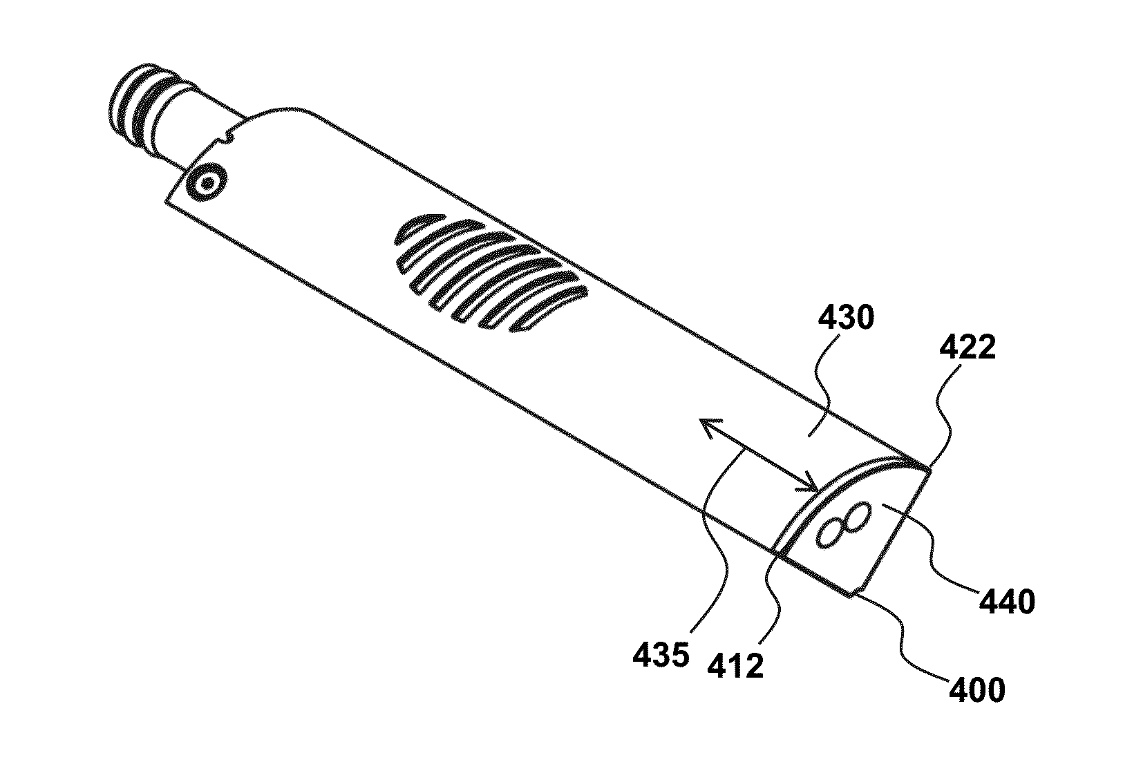
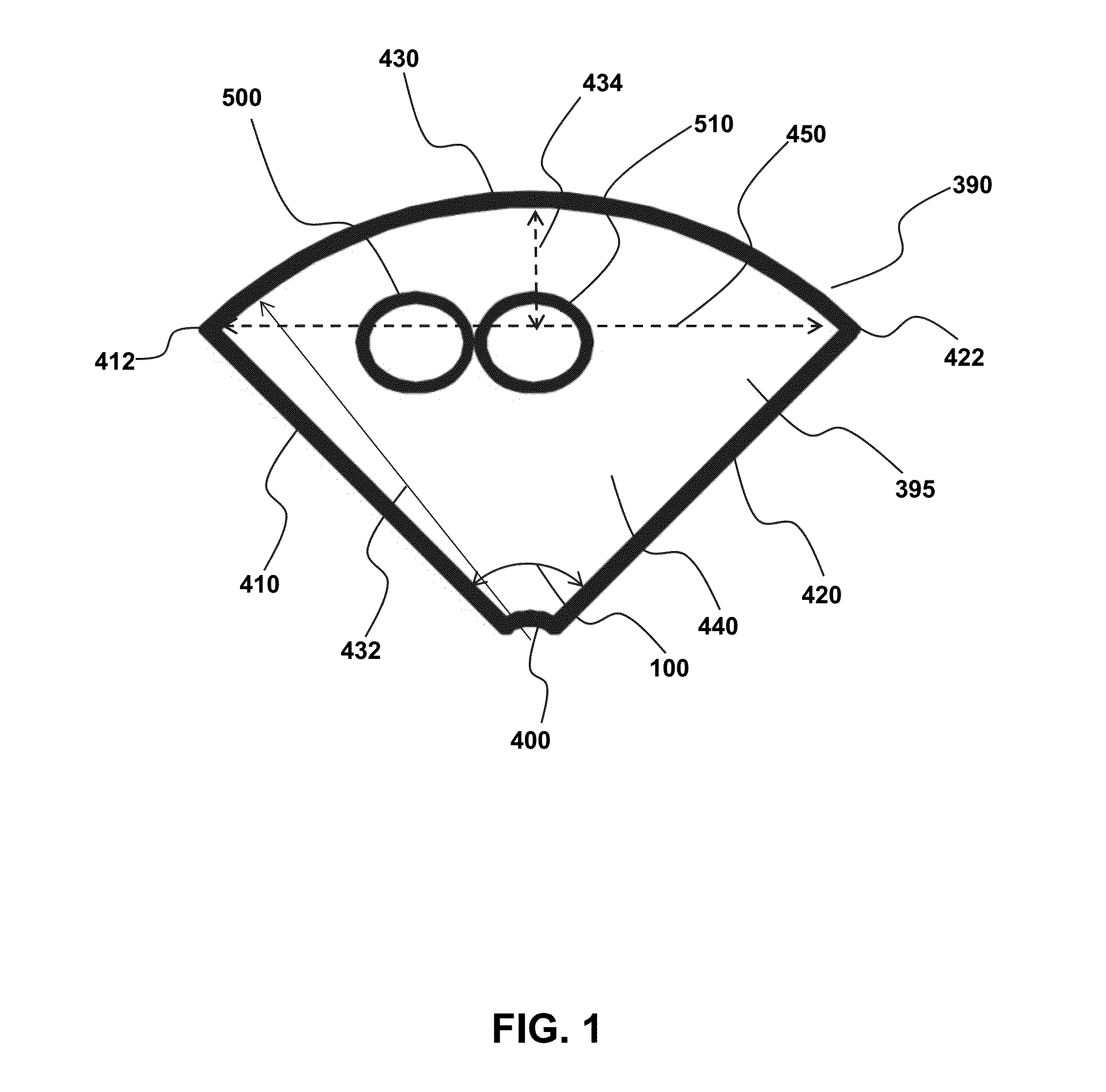
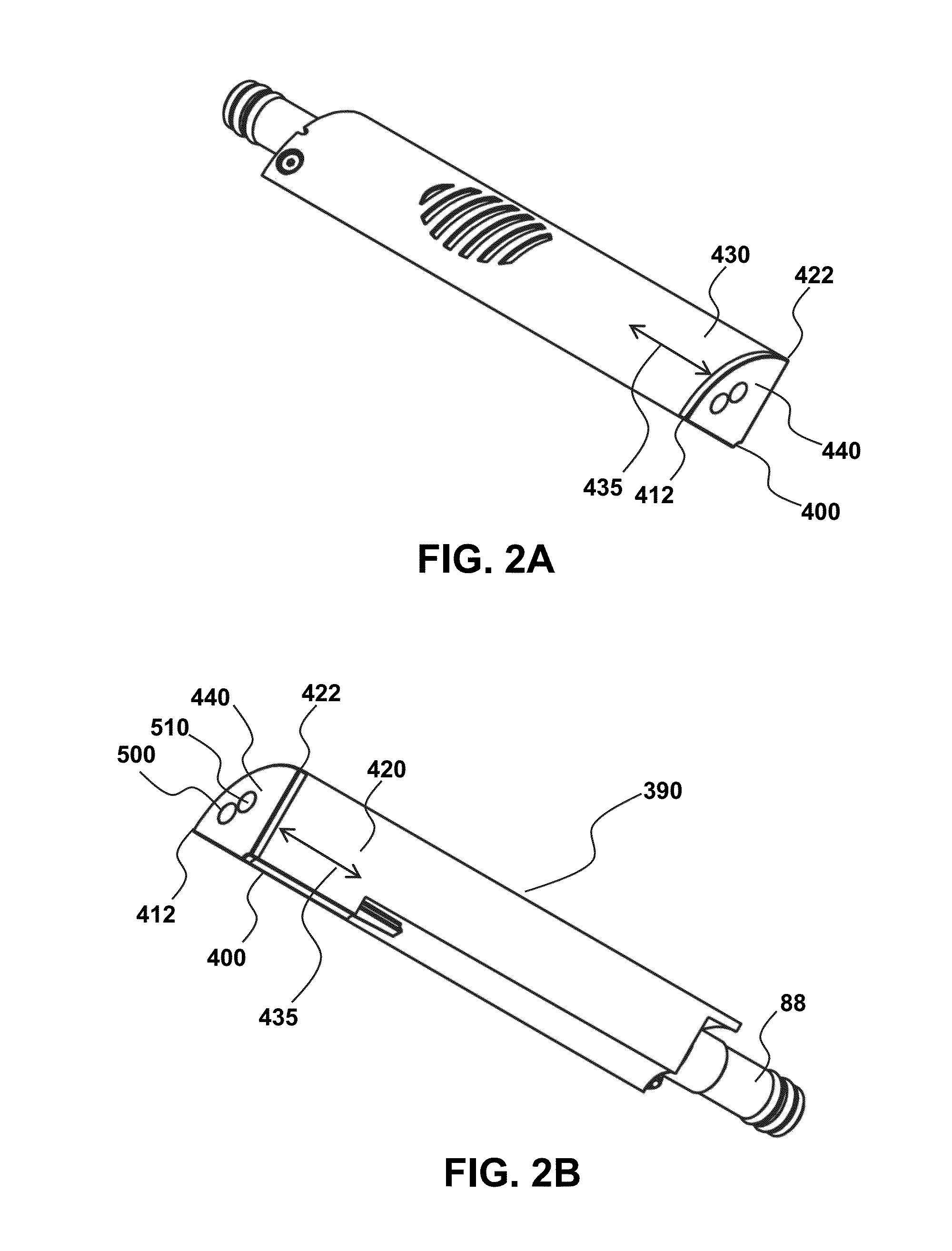
[0081]Referring to FIG. 1, a distal sending end 395 is illustrated from a top-view to show a sensor housing 390 comprising a vertex region 400 from which a first surface 410 and second surface 420 extend to first surface end point 412 and second surface end ...

example 2

Optical Components in Distal Sensing End

[0089]Optical components positioned within the distal sensing end volume are schematically illustrated in FIG. 4. Optical light source 520, such as a large diameter (5 mm or larger) LED is optically connected to the emission window 500 for providing electromagnetic radiation generated by the light source to a fluid sample volume 530 positioned adjacent to the distal sensing surface 440. Also illustrated is reference photodetector 540 in optical communication with a portion of the electromagnetic radiation emitted from the light source 520 and signal photodetector 550 in optical communication with collection window 510 for detecting light transmitted through the collection window that is associated with scattering by or fluorescence of material in the fluid sample volume 530. A beam splitter 560 may be positioned in optical communication with the light source 520 to reflect a portion of the electromagnetic radiation to the reference detector 54...

example 3

Sensor Guard

[0093]The sensors provided herein may be used with a sensor guard, such as the sensor guard 176 of FIG. 6A having a plurality of passages 174 with interspersed solid guard sections 173. FIG. 6B is a sectional view along a central plane of the distal end of the sensor to the sensor guard cap 177 of sensor guard 170. An internal surface 270 of sensor guard cap 177 faces the distal sensing surface 60, and is separated by a sample distance 271. The sample distance 271 forms a corresponding sensing volume, a portion of which will correspond to a sample volume 533 that includes a sensing height 700 (defined as the distance between the sensor end and the particle in the fluid sample interacting with the incident light) and a nominal light path from the light source 702 and corresponding scattering by and / or fluorescence light path 704 of particles in the fluid sample. Accordingly, nominal optical path length is the sum of the length of 702 (light path from optical source to sam...


PUM

PropertyMeasurementUnit
angleaaaaaaaaaa
surface areaaaaaaaaaaa
vertex angleaaaaaaaaaa

Abstract

Provided are turbidometers and fluorometers having a unique form-factor to accommodate a number of optical components in a confined geometry. This provides the ability to compensate for change in light intensity from an optical source even in a closed-loop manner. The ability to package reference and signal detectors, along with a relatively large diameter LED light source in a confined geometry is particularly suited for applications requiring small-diameter sensors, such as multi-parameter sonde devices having a total diameter that is in the sub-two inch range.

Description

CROSS-REFERENCE TO RELATED APPLICATIONS[0001]This application claims the benefit of priority of U.S. Provisional Application Ser. Nos. 62 / 115,593 and 62 / 115,466 filed Feb. 12, 2015 and 62 / 077,528 filed Nov. 10, 2014, each of which are hereby incorporated by reference to the extent not inconsistent herewith.BACKGROUND OF INVENTION[0002]Provided herein are water quality instruments containing multiple sensors for measuring a plurality of water-related parameters. The sensors are uniquely configured to have an extremely high form factor so that they may be contained within a housing that minimizes dead space between sensors and within the housing, with the individual sensor ends forming a single continuous sensing surface. This provides a number of functional benefits in the field of multi-parameter sondes and related sensing methods, including for in-situ applications where the total diameter of the sonde instrument is desirably less than 4″ or less than 2″.[0003]The sensors described...

Claims


Application Information

Patent Timeline
Patent Type & Authority Applications(United States)
IPC IPC(8): G01N21/53
CPCG01N2201/068G01N21/532G01N27/07G01N33/18
Inventor BALTZ, NATHAN T.SEWELL, STEVEN COLLIN
Owner INSITU INC
Why Eureka
Try Eureka