Occupancy based demand controlled utility system

a utility system and occupancy-based technology, applied in the direction of static/dynamic balance measurement, wireless commuication services, high-level techniques, etc., can solve the problems of delay in shutting off lights and unnecessary energy consumption, and achieve the effect of significant energy efficiency, inexpensive and simple implementation

Active Publication Date: 2016-05-19
AIKEN THOMAS DAVID +1
View PDF0 Cites 24 Cited by
  • Summary
  • Abstract
  • Description
  • Claims
  • Application Information

AI Technical Summary

Benefits of technology

[0025]Consequently, the present invention affords significant energy efficiencies not enabled by the prior art in this field. Moreover, this system is relatively inexpensive and simple to implement, unlike systems requiring carbon dioxide (CO2) monitoring and / or sophisticated active tags.

Problems solved by technology

Importantly, these types of sensors call for a delay in shutting off lights after no motion or sound is detected, in case occupants are still present.
It becomes a nuisance if occupants are still present and the lights go off, and the delay itself, typically 20 minutes, causes unnecessary energy consumption if the space is indeed vacant.

Method used


Image

  • Occupancy based demand controlled utility system
  • Occupancy based demand controlled utility system
  • Occupancy based demand controlled utility system

Examples


first embodiment

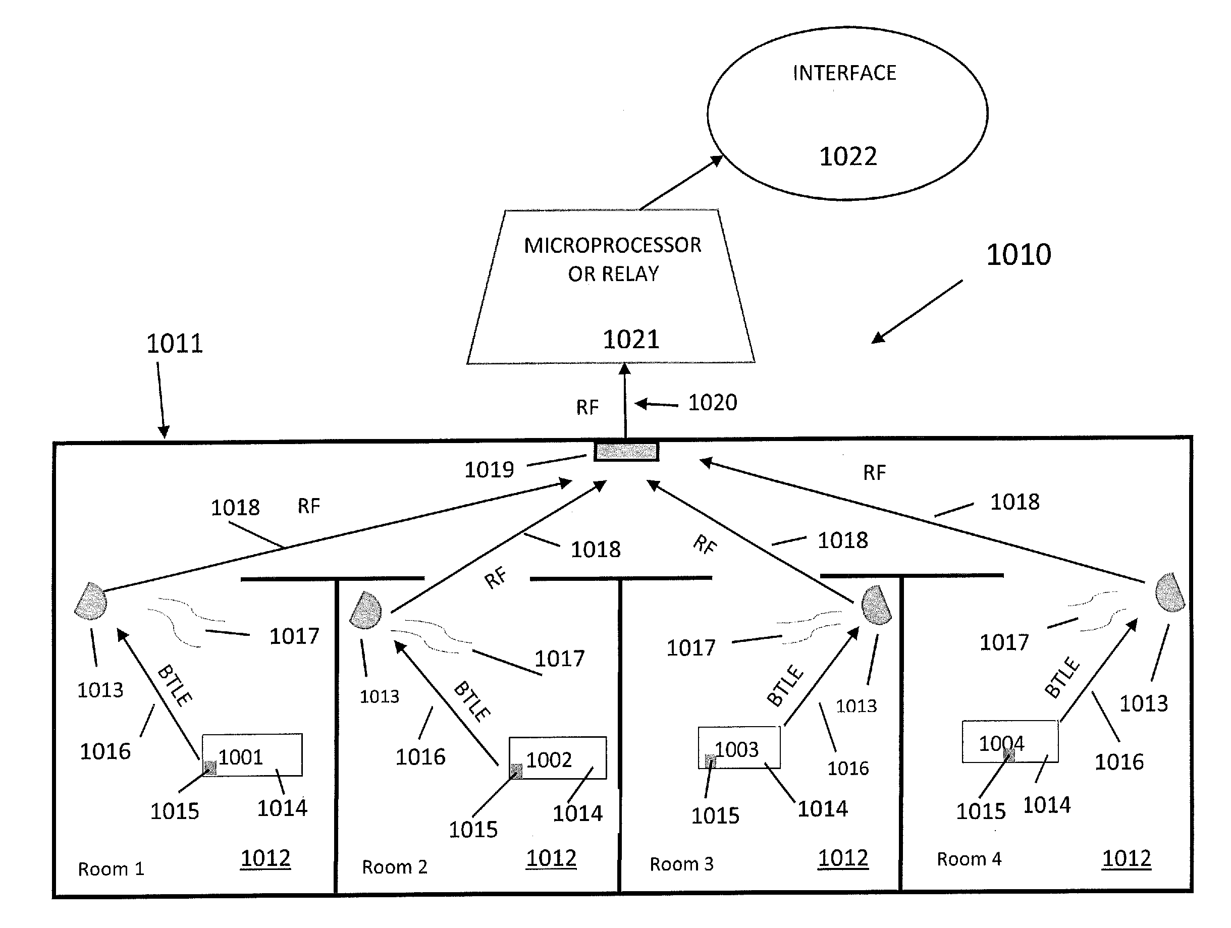
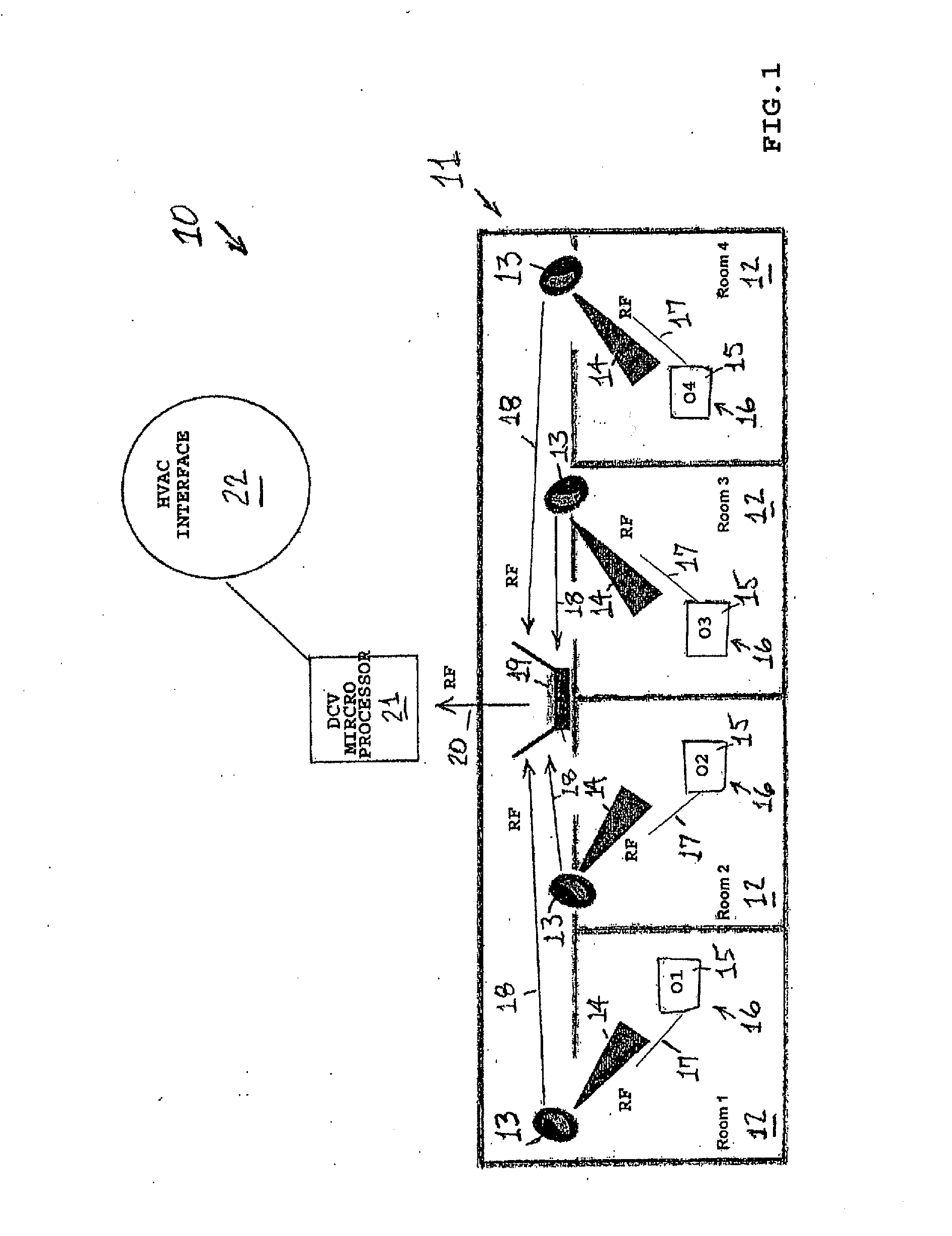
[0047]FIG. 1 depicts a schematic apparatus configuration of the present invention 10, which uses passive tags. For illustrative purposes, this figure focuses on one ventilation zone 11 of a building that has multiple ventilation zones. The same basic apparatus configuration would be replicated in the other ventilation zones of the building. The exemplary ventilation zone 11 comprises four rooms 12, which are labeled Rooms 1-4. Obviously, depending on the floor plan and ventilation system of the building, each ventilation zone 11 can have more or fewer rooms 12 than are depicted in this figure. Hence, the number of rooms 12 indicated here is for illustrative purposes only.

embodiment 10

[0048]In each room 12, there are one or more sensors that are tag readers 13. There is one tag reader 13 per room 12, but multiple tag readers 13 may be required for rooms that are very large and / or have very complex configurations. In the preferred embodiment 10, the tag reader(s) 13 in each room 12 continuously transmit(s) RF search signals 14 throughout the room 12. The search signals 14 are detected by passive RFID tags 15 implanted in ID badges 16 issued to all building occupants and visitors. The RFID tags 15 respond to the search signals 14 by transmitting RF tag signals 17 back to the tag reader 13. The tag signal 17 for each RFID tag 15 transmits a digital ID code assigned to the particular ID badge 16 in which the RFID tag 15 is implanted. The tag reader(s) 13 then compile a running list of ID codes associated with the RFID tags 15 that are present in the room 12.

[0049]The tag reader(s) 13 in each room 12 at specified intervals transmit(s) RF reader signal(s) 18 to a zonal...

second embodiment

[0056]FIG. 3 depicts a schematic apparatus configuration of the present invention 10, which uses active tags. For illustrative purposes, this figure focuses on one ventilation zone 11 of a building that has multiple ventilation zones. The same basic apparatus configuration would be replicated in the other ventilation zones of the building. The exemplary ventilation zone 11 comprises four rooms 12, which are labeled Rooms 1-4. Obviously, depending on the floor plan and ventilation system of the building, each ventilation zone 11 can have more or fewer rooms 12 than are depicted in this figure. Hence, the number of rooms 12 indicated here is for illustrative purposes only.

[0057]In each room 12, there are one or more sensors that are infra-red (IR) emitters 13. There is one IR emitter 13 per room 12, but multiple IR emitters 13 may be required for rooms that are very large and / or have very complex configurations. In the embodiment 10, the IR emitter(s) 13 in each room 12 continuously e...


PUM


Abstract

To control lighting and other utilities in buildings based upon occupancy, mountable sensors are used to detect low energy radio frequencies emitted from devices, or tags, worn or carried by occupants. In a demand control system, identification (ID) codes embedded in tags worn by occupants are detected in each room by a tag sensor and may wirelessly communicate to a zonal compiler that determines zonal occupancy. The zonal occupancy count is transmitted to an interface relay that immediately adjusts the intensity and rate of the specific utility. HVAC systems may also be tied into the system to have adjustments made to the intensity and rate of ventilation as done with the lighting in this system. This system has many advantages over current systems such as not being dependent upon movement of an occupant or following the heat signature of an occupant that both may lead to false readings and delay in adjusting the specific building utility to save energy and costs.

Description

CROSS-REFERENCE TO RELATED APPLICATION(S)[0001]The present application is a Continuation-in-Part of U.S. patent application Ser. No. 12 / 591,803, filed on Dec. 2, 2009, the disclosure of which is incorporated herein by reference.FIELD OF INVENTION[0002]The present invention relates to the field of controlling utility services and, more particularly, to the field of electrical lighting for buildings. HVAC and, more particularly, ventilation systems for buildings may also utilize the invention. The present invention specifically addresses demand-controlled systems, in which the rate of utility use is determined based on actual occupancy levels in the controlled zones, rather than default occupancy levels.BACKGROUND[0003]Both environmental and economic concerns in recent years have driven a move toward conserving energy in building utilities such as lighting and heating, ventilation and air conditioning (HVAC). Various methods have been used in the past to conserve energy in these servi...

Claims


Application Information

Patent Timeline
Patent Type & Authority Applications(United States)
IPC IPC(8): G05B15/02H04W4/00F24F11/00H05B37/02H04W4/80
CPCG05B15/02H05B37/0227F24F11/006H04W4/008H05B37/0272F24F11/0001F24F11/30F24F2120/10F24F11/62H04W4/80Y02D30/70H05B47/19H05B47/115Y02B20/40F24F11/46F24F11/63
Inventor AIKEN, THOMAS DAVIDWILLIAMS, MICHAEL EUGENE
Owner AIKEN THOMAS DAVID
Why Eureka
Try Eureka