
Measurement system and measurement method

Active Publication Date: 2016-05-19
TOKYO ELECTRON LTD
View PDF13 Cites 22 Cited by
  • Summary
  • Abstract
  • Description
  • Claims
  • Application Information

AI Technical Summary

Benefits of technology

The present invention relates to a measurement system for measuring the consumption of a focus ring in a plasma etching apparatus. The system includes a sensor substrate with a distance sensor and a measurement unit including a transfer instruction unit and an acquisition unit. The sensor substrate is transferred into the processing chamber and the distance sensor measures the distance between the sensor substrate and the focus ring. The measurement unit then calculates the consumption of the focus ring based on the physical information obtained from the distance sensor. The technical effect of this invention is to provide a more accurate measure of the consumption of the focus ring, which helps to improve the efficiency of the plasma etching process.

Problems solved by technology

Therefore, an etching rate is changed at the peripheral portion of the target substrate and this may result in deterioration of device characteristics.
However, once exposed to an atmospheric atmosphere, the inside of the processing chamber needs to return to a vacuum state in order to continue the processing, which requires a time.
Therefore, in the case of measuring the thickness of the focus ring, a production line is stopped during such a process and this results in decrease of a productivity.
In order to install those windows, the plasma etching apparatus needs to be modified, which increases a manufacturing cost of the plasma etching apparatus.
In addition, a degree of freedom in design of the plasma etching apparatus is decreased because it is not possible to provide a member on optical paths of the laser beam and the reflection light.

Method used


Image

  • Measurement system and measurement method
  • Measurement system and measurement method
  • Measurement system and measurement method

Examples


Embodiment Construction

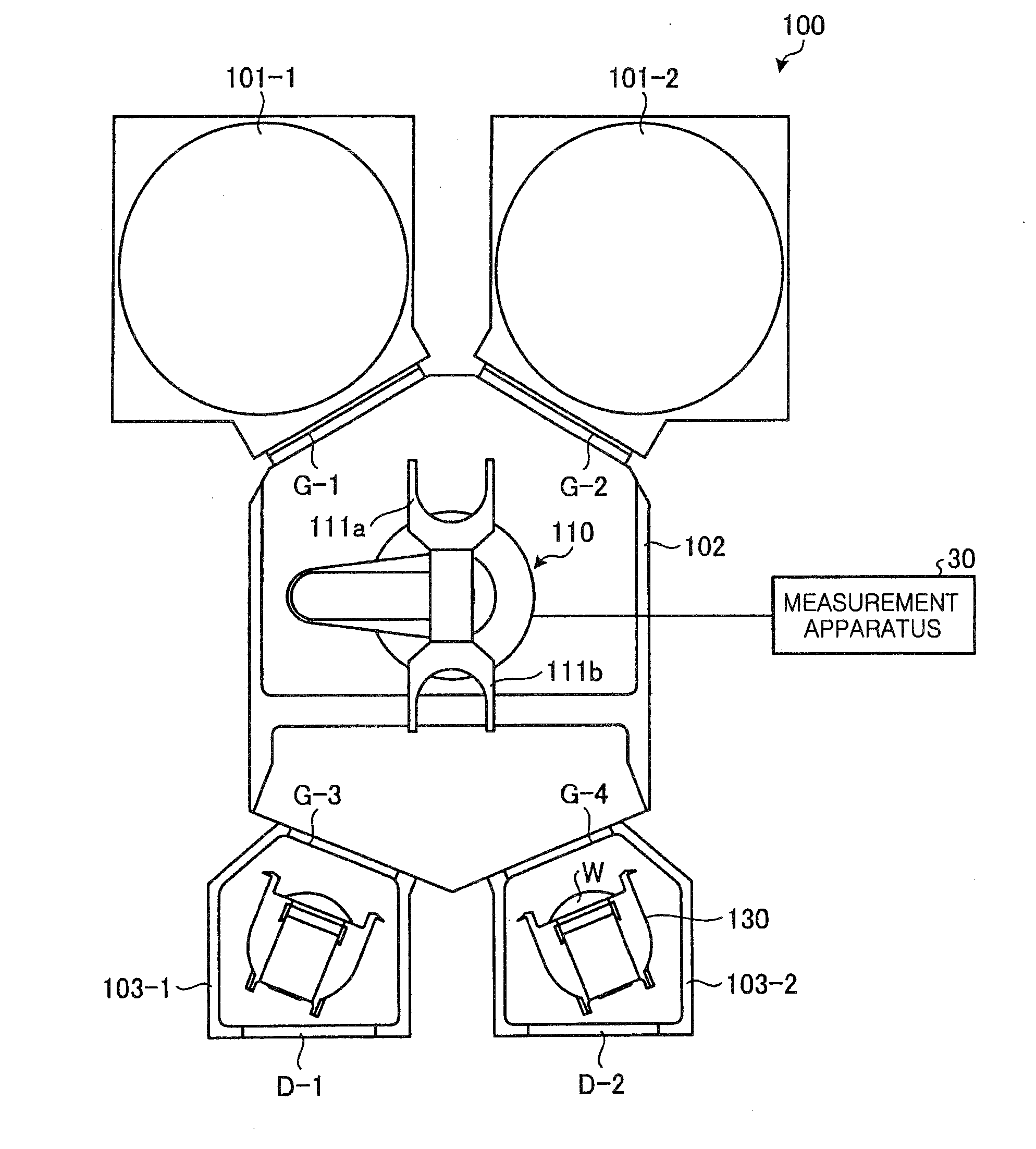
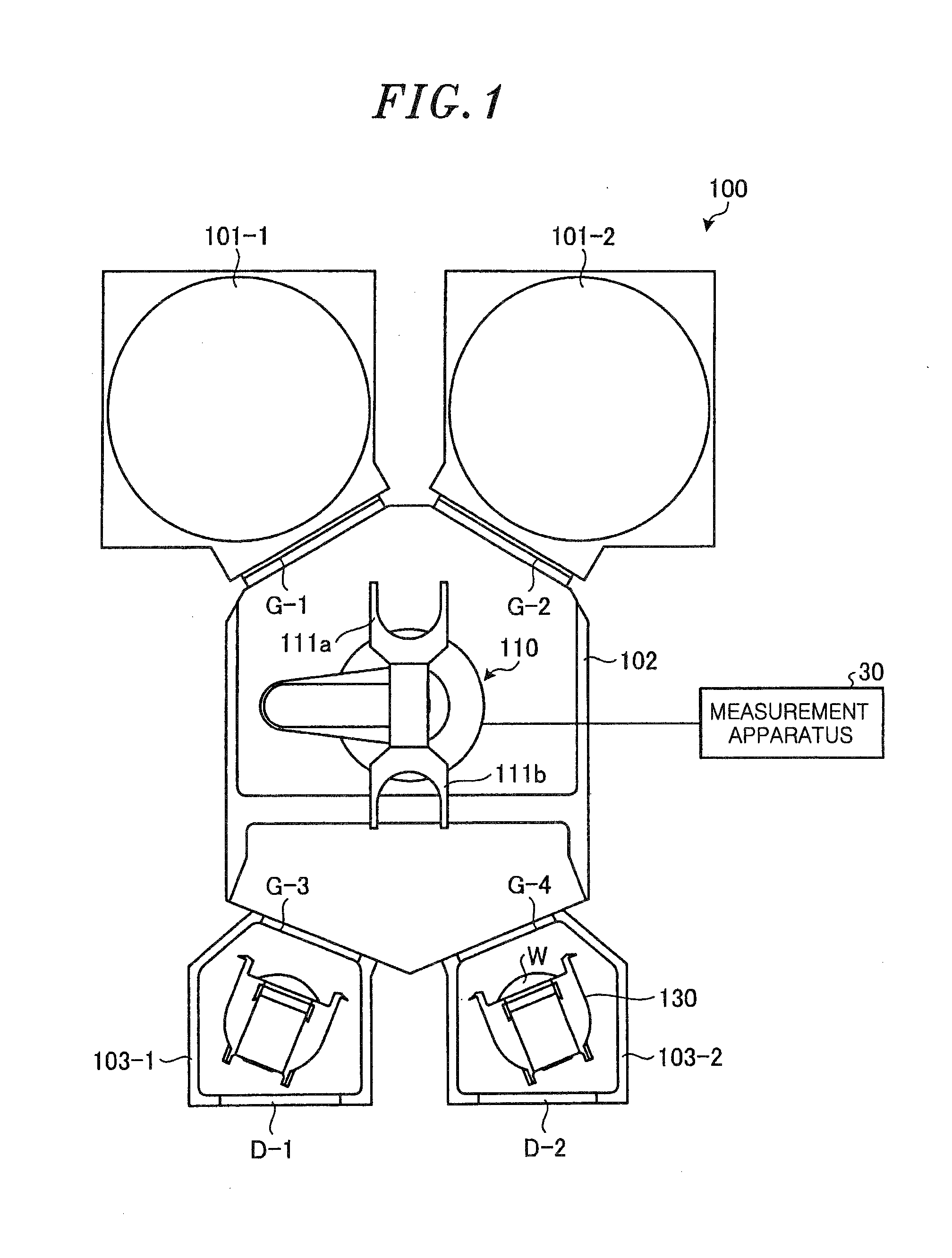
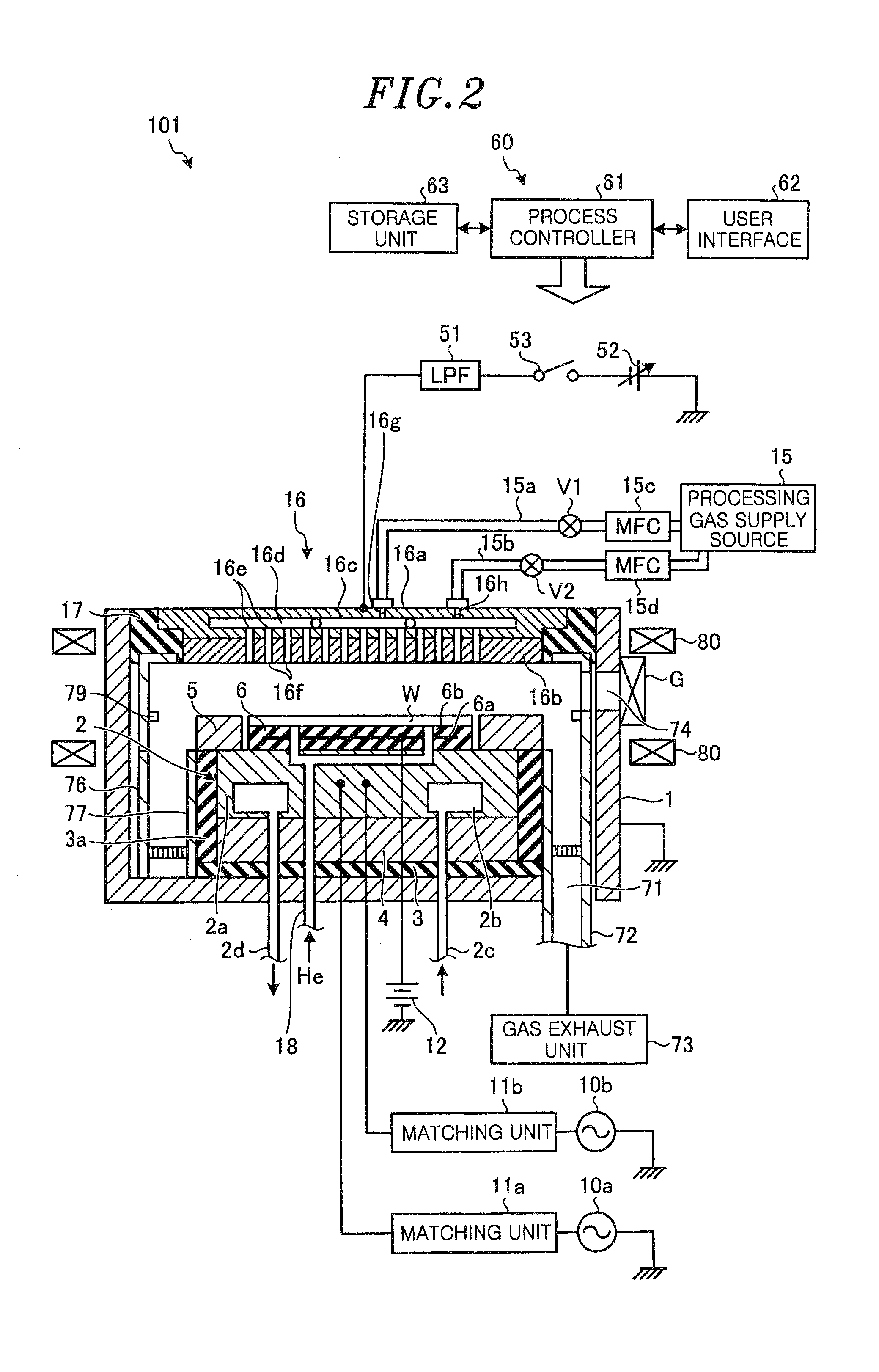
[0022]A measurement system for measuring a consumption amount of a focus ring in a plasma etching apparatus including a processing chamber configured to accommodate a target substrate, a lower electrode provided in the processing chamber and configured to mount thereon the target substrate loaded into the processing chamber by a transfer unit, and the focus ring surrounding a periphery of the lower electrode, the measurement system includes: a sensor substrate having a distance sensor; and a measurement unit configured to measure a consumption amount of the focus ring, wherein the measurement unit includes: a transfer instruction unit configured to instruct the transfer unit to transfer the sensor substrate into the processing chamber; an acquisition unit configured to acquire information on a physical amount corresponding to a distance from the distance sensor to the focus ring, which is measured by the distance sensor; and a measurement unit configured to measure a consumption amo...


PUM


Abstract

A measurement system for measuring a consumption amount of a focus ring in a plasma etching apparatus including a processing chamber, a lower electrode and the focus ring surrounding a periphery of the lower electrode, comprises a sensor substrate having a distance sensor and a measurement unit configured to measure a consumption amount of the focus ring. The measurement unit includes a transfer instruction unit, an acquisition unit and a measurement unit. The transfer instruction unit is configured to instruct a transfer unit to transfer the sensor substrate into the processing chamber. The acquisition unit is configured to acquire information on a physical amount corresponding to a distance from the distance sensor to the focus ring, which is measured by the distance sensor. The measurement unit is configured to measure a consumption amount of the focus ring based on the acquired information on the physical amount.

Description

CROSS-REFERENCE TO RELATED APPLICATIONS[0001]This application claims priority to Japanese Patent Application No. 2014-234724 filed on Nov. 19, 2014, the entire contents of which are incorporated herein by reference.FIELD OF THE INVENTION[0002]The disclosure relates to a measurement system and a measurement method.BACKGROUND OF THE INVENTION[0003]In a plasma etching apparatus, uniformity of plasma distribution near a peripheral portion of a target substrate is improved by providing a focus ring around a lower electrode on which the target substrate is mounted. However, the focus ring is gradually etched together with the target substrate during an etching process using a plasma. If the focus ring is etched, the uniformity of the plasma distribution at the peripheral portion of the target substrate is decreased. Therefore, an etching rate is changed at the peripheral portion of the target substrate and this may result in deterioration of device characteristics.[0004]In order to measur...

Claims


Application Information

Patent Timeline
IPC IPC(8): H01J37/32G01B7/06
CPCH01J37/32935H01J2237/3343G01B7/08H01J37/32642H01J37/32917H01J37/3299G01B7/023
Inventor KAMATA, KOJIIKARI, HIROSHI
Owner TOKYO ELECTRON LTD
Learn More