Super junction field effect transistor with internal floating ring

Active Publication Date: 2016-05-19
LITTELFUSE INC
View PDF7 Cites 5 Cited by
  • Summary
  • Abstract
  • Description
  • Claims
  • Application Information

AI Technical Summary

Benefits of technology

The patent describes a method to improve the performance of semiconductor devices by using a floating ring-shaped P-type column. This column helps to increase the avalanche breakdown voltage of the device and reduces the impact ionization in adjacent regions, resulting in a more robust and reliable device design. The method can also help to mitigate the effects of process variations during fabrication. Overall, this patent provides a technical solution for improving the performance of semiconductor devices.

Problems solved by technology

During fabrication, if the concentration of N-type dopants within the charge compensation region becomes undesirably imbalanced with respect to the concentration of P-type dopants within the charge compensation region, then the breakdown voltage requirement will not be satisfied.
Fabricating the N-channel field effect transistor device to meet a particular breakdown voltage requirement requires tight process control because process variation can result in charge imbalance between the concentration of P-type dopants and N-type dopants.
Usually, such charge imbalance caused by process variations occurs at the corners and edges of an active area of the device causing the formation of local low voltage areas and in a weak device.
In addition, conventional super junction fabrication processes are undesirably expensive because forming P− type columns involves many delicate process steps.
Such process variations may cause a charge imbalance along edges and corners along the P− type columns of the internal active area.

Method used


Image

  • Super junction field effect transistor with internal floating ring
  • Super junction field effect transistor with internal floating ring
  • Super junction field effect transistor with internal floating ring

Examples


Embodiment Construction

[0027]Reference will now be made in detail to some embodiments of the invention, examples of which are illustrated in the accompanying drawings. In the text and drawings, the dopant labels N++, N+, N−, N, P+, P−, and P are only very loose general descriptions of relative dopant concentrations. A particular dopant label appearing in the text below has meaning within the local context of its usage. In the text and drawings, the term P type is sometimes used not as a description of a relative dopant concentration, but rather is used as a broad term to denote semiconductor material that may be P− type, or may be P type, or may be P+ type, or that may include sub-regions of various P type dopant concentrations.

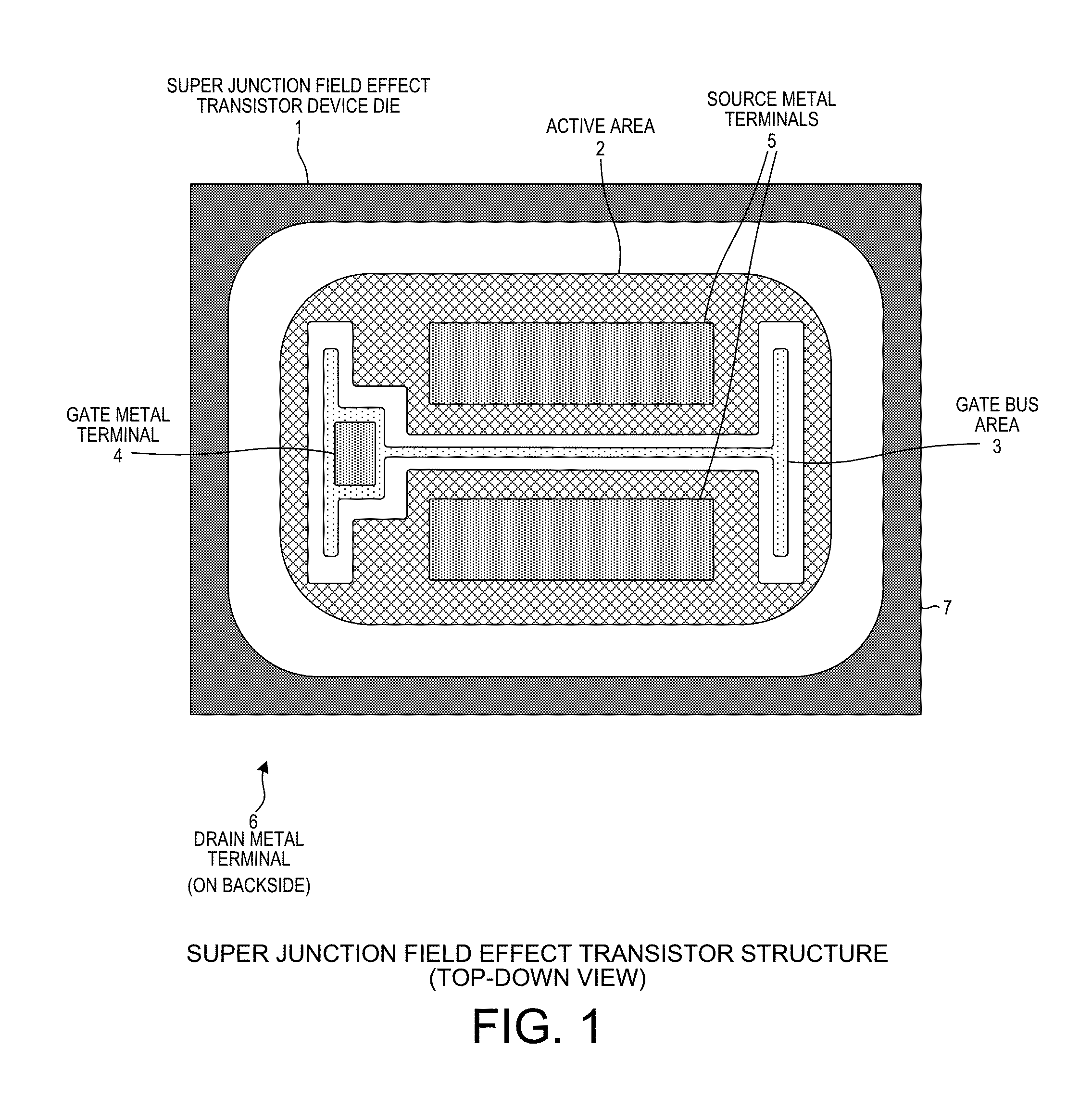
[0028]FIG. 1 is a top-down diagram of a Super Junction Field Effect Transistor (FET) device die 1 in accordance with one novel aspect. Such a Super Junction FET device die 1 is also loosely referred to as a Super Junction Metal Oxide Semiconductor Field Effect Transistor (MOSFET). ...


PUM


Abstract

A Super Junction Field Effect Transistor (FET) device includes a charge compensation region disposed on a substrate of semiconductor material. The charge compensation region includes a set of strip-shaped P− type columns, a floating ring-shaped P− type column that surrounds the set of strip-shaped P− type columns, and a set of ring-shaped P− type columns that surrounds the floating ring-shaped P− type column. A source metal is disposed above portions of the charge compensation region. The source metal contacts each of the strip-shaped P− type columns and each of the ring-shaped P− type columns. An oxide is disposed between the floating P− type column and the source metal such that the floating P− type column is electrically isolated from the source metal. The device exhibits a breakdown voltage that is 0.2% greater than if the floating P− type column were to contact the source metal.

Description

TECHNICAL FIELD[0001]The described embodiments relate generally to Super Junction field effect transistors and techniques for making rugged Super Junction field effect transistors.BACKGROUND INFORMATION[0002]Super junction techniques are often employed to fabricate an N-channel field effect transistor device. Such an N-channel field effect transistor device can be made whose drift region includes what is called a “charge compensation region”. The N-channel field effect transistor device is typically made to meet a particular breakdown voltage requirement. During fabrication, if the concentration of N-type dopants within the charge compensation region becomes undesirably imbalanced with respect to the concentration of P-type dopants within the charge compensation region, then the breakdown voltage requirement will not be satisfied. To maintain charge balance between the concentration of P-type dopants and N-type dopants, very tight process control is required. Fabricating the N-chann...

Claims


Application Information

Patent Timeline
IPC IPC(8): H01L29/78H01L29/417H01L29/66H01L29/06
CPCH01L29/7811H01L29/0634H01L29/66712H01L29/0692H01L29/41741H01L29/0623
Inventor SEOK, KYOUNG WOOK
Owner LITTELFUSE INC
Why Eureka
Try Eureka