Method of Selecting a Battery Pack Charging Protocol

a battery pack and charging protocol technology, applied in the field of methods, can solve the problems of reduced level, many inherent limitations of such a power source, and vehicle emissions still harmful pollution, and achieve the effect of maximizing battery lifetime characteristics

Active Publication Date: 2016-05-26
ATIEVA USA INC
View PDF6 Cites 6 Cited by
  • Summary
  • Abstract
  • Description
  • Claims
  • Application Information

AI Technical Summary

Benefits of technology

[0006]The present invention provides a method of optimizing the charging parameters for a battery pack coupled to the electric drive train of a vehicle, the method comprising the steps of (i) accepting a set of user determined travel information comprised of an intended departure time and an intended travel distance, where the set of user determined travel information is accepted by a vehicle system controller; (ii) determining an optimal charge level for the battery pack, where the optimal charge level maximizes a battery lifetime characteristic while providing sufficient energy for the vehicle to travel the intended travel distance, and where the step of determining the optimal charge level is performed by the system controller; (iii) determining an optimal charging rate for the battery pack, where the optimal charging rate maximizes the battery lifetime characteristic while being sufficient to complete charging of the battery pack to the optimal charge level prior to the intended departure time, and where the step of determining the optimal charging rate is performed by the system controller; and (iv) charging the battery pack of the vehicle to the optimal charge level, where the charging step is performed at the optimal charging rate. In general, the intended departure time identifies the first expected time of usage for the vehicle after completion of the step of battery pack charging while the intended travel distance identifies the total expected travel distance during a period of time occurring between completion of the charging step and the next (i.e., subsequent) charging cycle. The user determined travel information may be input via a user interface coupled to the system controller; alternately, the user determined travel information may be input from a remote device coupled to the system controller via a communication port; alternately, the user determined travel information may be input from a remote device coupled to the system controller via a wireless communication link.

Problems solved by technology

While hybrid vehicles provide improved gas mileage and lower vehicle emissions, due to their inclusion of an internal combustion engine they still suffer from many of the inherent limitations of such a power source.
For example, during operation the vehicle still emits harmful pollution, albeit at a reduced level compared to a conventional vehicle.
Additionally, due to the inclusion of both an internal combustion engine and an electric motor(s) with its accompanying battery pack, the drive train of a hybrid vehicle is typically much more complex, resulting in increased cost and weight.
While the electric drive trains used in all-electric vehicles have proven to be highly reliable, the concerns felt by many people relating to the limited driving range of a typical electric vehicle have led to fewer car sales than would otherwise be expected, especially given the performance and reliability of such cars.
As a result of not fully understanding the effect that charge rate and state-of-charge (SOC) have on battery life, even if a vehicle permits the driver to set charging parameters, a typical car owner finds it difficult to optimize these parameters.

Method used


Image

  • Method of Selecting a Battery Pack Charging Protocol
  • Method of Selecting a Battery Pack Charging Protocol
  • Method of Selecting a Battery Pack Charging Protocol

Examples


Embodiment Construction

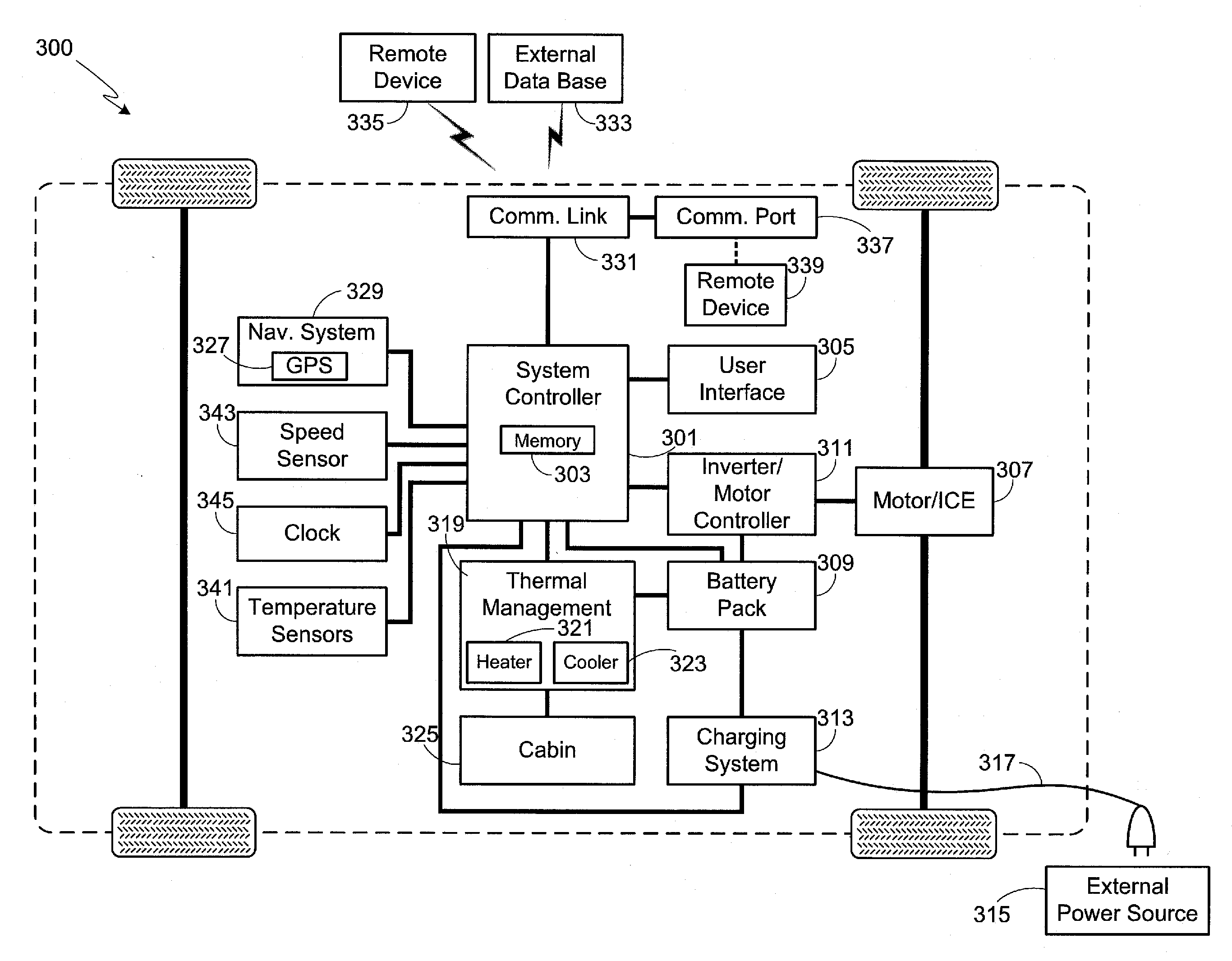
[0021]As used herein, the singular forms “a”, “an” and “the” are intended to include the plural forms as well, unless the context clearly indicates otherwise. The terms “comprises”, “comprising”, “includes”, and / or “including”, as used herein, specify the presence of stated features, process steps, operations, elements, and / or components, but do not preclude the presence or addition of one or more other features, process steps, operations, elements, components, and / or groups thereof. As used herein, the term “and / or” and the symbol “ / ” are meant to include any and all combinations of one or more of the associated listed items. Additionally, while the terms first, second, etc. may be used herein to describe various steps, calculations, or components, these steps, calculations, or components should not be limited by these terms, rather these terms are only used to distinguish one step, calculation, or component from another. For example, a first calculation could be termed a second ca...


PUM


Abstract

A method is provided for optimizing the charging protocol used when charging the battery pack of an electric vehicle, where optimization is based, in part, on the user's intended departure time and intended travel distance. Based on the user's travel information the process determines (i) an optimal charge level that maximizes the battery pack's lifetime while assuring that there is sufficient energy for the vehicle to travel the intended distance and (ii) an optimal charging rate that maximizes the battery pack's lifetime while assuring that the battery pack is charged to the optimal charge level prior to the intended time of departure. Safety margins may be added to the user's travel information, thus insuring that the car is charged and ready for use if the user decides to leave earlier than expected, or if the travel takes a larger charge than expected.

Description

FIELD OF THE INVENTION[0001]The present invention relates generally to an electric vehicle and, more particularly, to a system and method that optimizes battery life.BACKGROUND OF THE INVENTION[0002]In response to the demands of consumers who are driven both by ever-escalating fuel prices and the dire consequences of global warming, the automobile industry is slowly starting to embrace the need for ultra-low emission, high efficiency cars. While some within the industry are attempting to achieve these goals by engineering more efficient internal combustion engines, others are incorporating hybrid or all-electric drive trains into their vehicle line-ups. To meet consumer expectations, however, the automobile industry must not only achieve a greener drive train, but must do so while maintaining reasonable levels of performance, range, reliability, and cost.[0003]The most common approach to achieving a low emission, high efficiency car is through the use of a hybrid drive train in whic...

Claims


Application Information

Patent Timeline
Patent Type & Authority Applications(United States)
IPC IPC(8): B60L11/18
CPCB60L11/1809B60L2240/62B60L2240/66B60L2240/80B60L2250/14B60L2250/18B60L2260/52B60L2260/54B60L58/12Y02T10/70Y02T10/72Y02T90/16
Inventor LIU, ALBERT
Owner ATIEVA USA INC
Why Eureka
Try Eureka