
Gas turbine and heat shield for a gas turbine

a gas turbine and heat shield technology, applied in the field of gas turbines, can solve the problems of disadvantage, considerable loss in efficiency of gas turbines, and components exposed to hot gas subject to high thermal loads, and achieve the effects of less temperature resistance, high thermal loading, and easy transportation

Inactive Publication Date: 2016-05-26
SIEMENS AG
View PDF4 Cites 0 Cited by
  • Summary
  • Abstract
  • Description
  • Claims
  • Application Information

AI Technical Summary

Benefits of technology

The patent describes a heat shield for a gas turbine that serves to protect components from thermal overloading and to resolve a conflict in the size of radial gaps. The heat shield is composed of ring segments with an abrasion coating that acts as a sacrificial layer to prevent damage to the rotor blades. The abrasion coating is designed to be gradually worn away during operation, allowing for very small radial gaps that improve the efficiency of the gas turbine. The dimensions of the ring segments are specified to ensure a uniform thickness for all segments, regardless of whether they are coated or not. This is achieved by using thermal coatings that have a greater thickness or layer thickness in the case of segments without abrasion coating. The use of thermal coatings is cost-effective compared to abrasion coatings.

Problems solved by technology

At such high temperatures of the hot gas, however, the components and parts exposed to said hot gas are subject to high thermal loads.
An oversized configuration of the radial gap however leads to considerable losses in efficiency of the gas turbine.
Owing to the open form of the ring, however, leakage of working medium, and possibly special sealing concepts, are necessary, for which reason said solution is considered to be disadvantageous.

Method used


Image

  • Gas turbine and heat shield for a gas turbine
  • Gas turbine and heat shield for a gas turbine
  • Gas turbine and heat shield for a gas turbine

Examples


Embodiment Construction

[0024]Parts which correspond to one another are each denoted by the same reference signs in all of the figures.

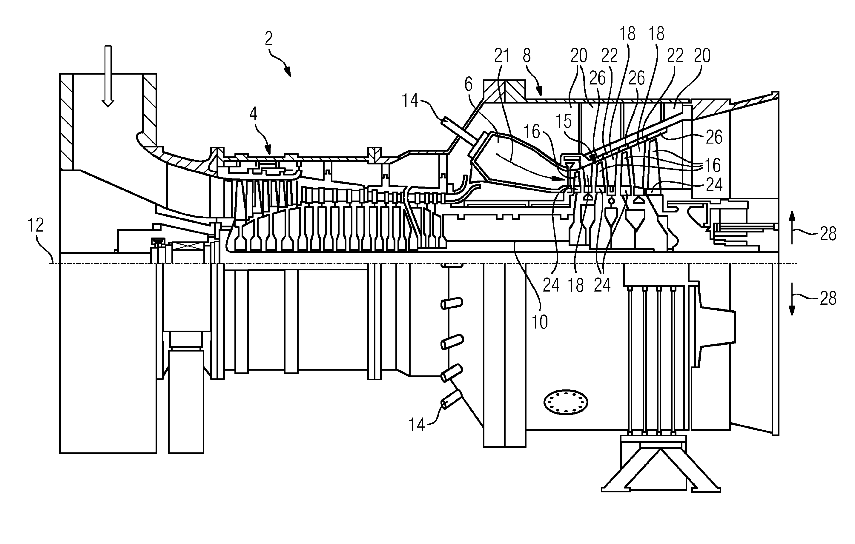
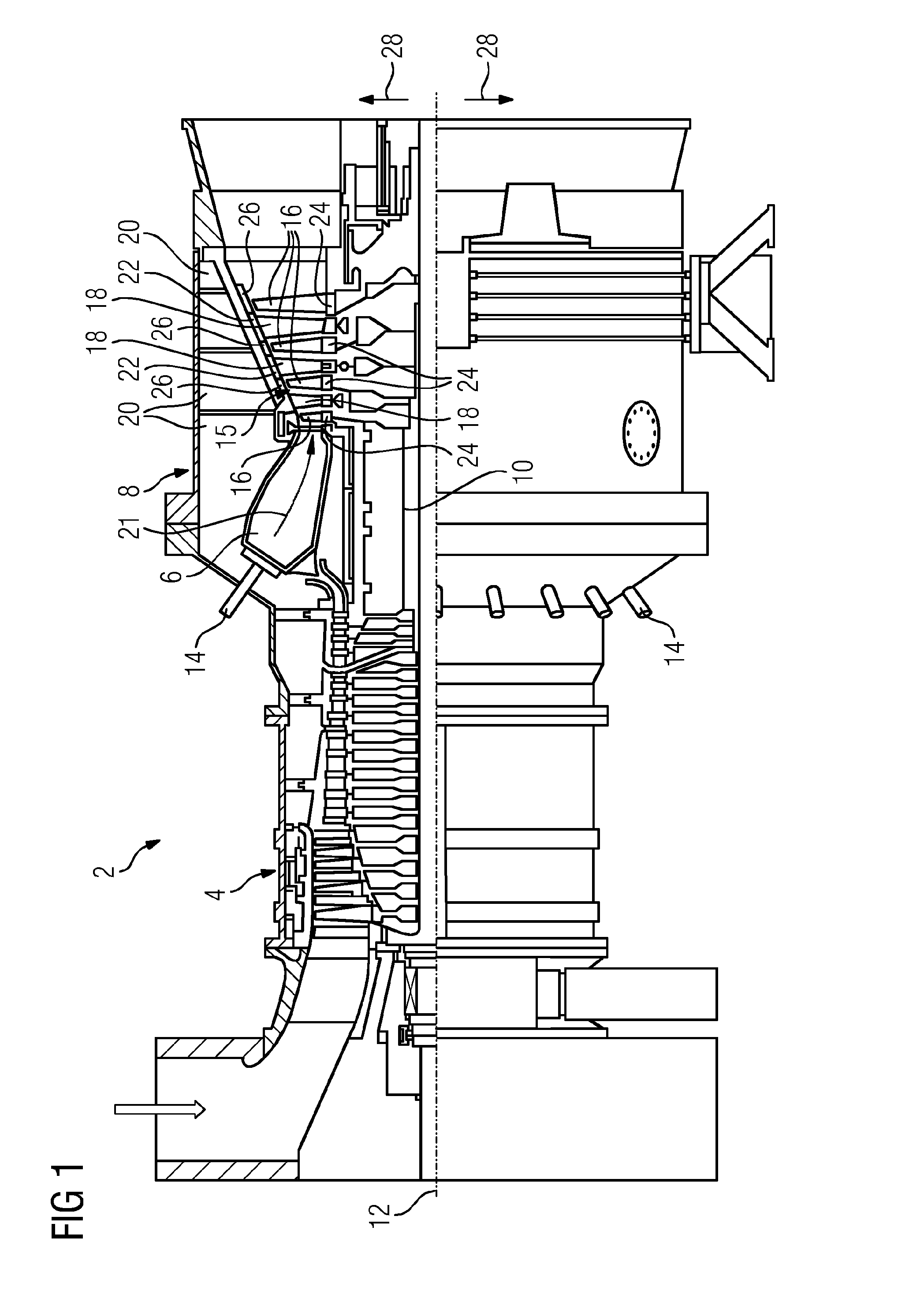
[0025]A gas turbine 2 described by way of example below is depicted in FIG. 1 and, in a manner known per se, has a compressor 4, a combustion chamber 6 and a turbine unit 8.

[0026]The combustion chamber 6, which is formed in the manner of a ring-shaped combustion chamber, is in this case equipped with a number of burners 14 for the combustion of a liquid or gaseous fuel, and opens into a hot-gas duct 15 of the turbine unit 8.

[0027]The turbine unit 8 and the compressor 4 are furthermore arranged on a common turbine shaft 10, also referred to as turbine rotor, to which a work machine (not illustrated) is also connected in non-positively locking fashion and which is mounted so as to be rotatable about a turbine axis 12. Furthermore, the turbine unit 8 has a number of rotor blades 16 which are arranged in the hot-gas duct 15 and which are connected to the turbine shaft 10 and wh...


PUM

PropertyMeasurementUnit
Fractionaaaaaaaaaa
Fractionaaaaaaaaaa
Thicknessaaaaaaaaaa

Abstract

A gas turbine includes a number of annular rotor blade rows coaxially mounted in a heating gas channel and a number of annular stator blade rows mounted between the rotor blade rows, wherein at least between two immediately adjacent stator blade rows a heat shield is positioned, which circumferentially surrounds the rotor blade row positioned between the two adjacent stator blade rows, and which has multiple ring segments, wherein at least one of the ring segments has an abrasion coating and at least one of the ring segments has no abrasion coating.

Description

CROSS REFERENCE TO RELATED APPLICATIONS[0001]This application is the US National Stage of International Application No. PCT / EP2014 / 063426 filed Jun. 25, 2014, and claims the benefit thereof. The International Application claims the benefit of German Application No. DE 102013212741.3 filed Jun. 28, 2013. All of the applications are incorporated by reference herein in their entirety.FIELD OF INVENTION[0002]The invention relates to a gas turbine comprising a number of ring-shaped rotor blade rows arranged coaxially in a hot-gas duct and a number of ring-shaped guide blade rows arranged between the rotor blade rows, and to a heat shield for a corresponding gas turbine.BACKGROUND OF INVENTION[0003]Gas turbines are used in many sectors for driving working machines, such as for example generators. Gas turbines are combustion engines in which a part of the energy stored in a fuel is utilized to generate a rotational movement of a turbine shaft. For this purpose, the fuel is mixed with air c...

Claims


Application Information

Patent Timeline
IPC IPC(8): F01D25/08F01D9/06F01D11/12F01D5/06F01D9/04
CPCF01D25/08F01D5/06F01D9/041F01D11/122F01D9/06F05D2220/32F05D2300/611F05D2240/15F05D2240/24F05D2260/231F05D2300/20F05D2300/502F05D2300/516F05D2240/12F01D11/12
Inventor AHMAD, FATHIPICKERT, URSULA
Owner SIEMENS AG
Learn More