Physical Quantity Measuring Device

Active Publication Date: 2016-05-26
HITACHI ASTEMO LTD
View PDF1 Cites 15 Cited by
  • Summary
  • Abstract
  • Description
  • Claims
  • Application Information

AI Technical Summary

Benefits of technology

[0012]According to the present invention, influence of heat, other than the heat of the gas to be mea

Problems solved by technology

Consequently, the number of harnesses for connecting various sensors and control d

Method used


Image

  • Physical Quantity Measuring Device
  • Physical Quantity Measuring Device
  • Physical Quantity Measuring Device

Examples


Embodiment Construction

[0024]An embodiment of the present invention will be described below with reference to the drawings. In the following embodiment, as an example of a physical quantity measuring device according to the present invention, a thermal flowmeter is exemplified which measures a flow rate and a humidity of a gas to be measured, and is mounted to an internal-combustion engine. A physical quantity to be measured of the gas to be measured and a device to be mounted is not limited to this example, as long as the following function and effect can be expected.

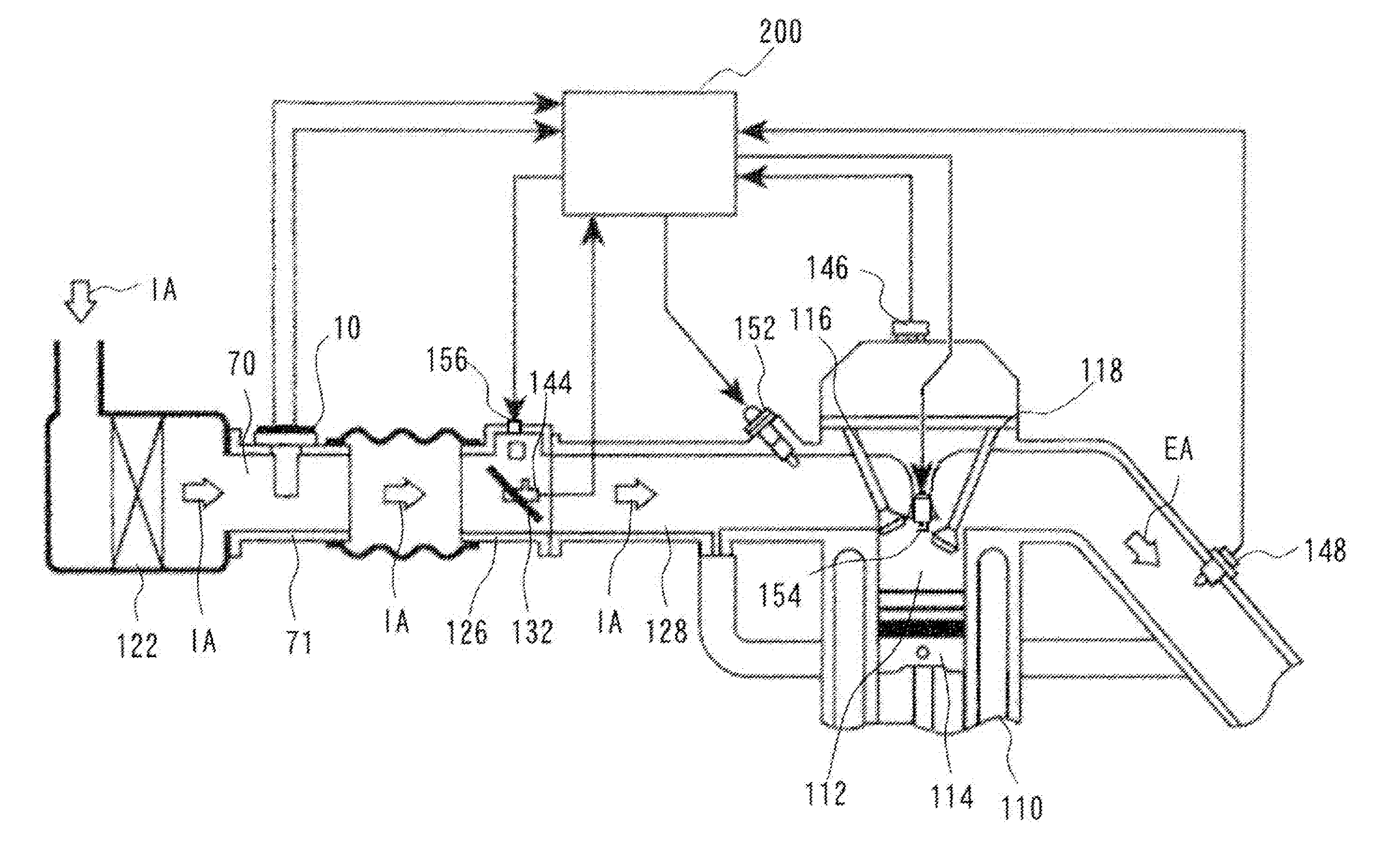
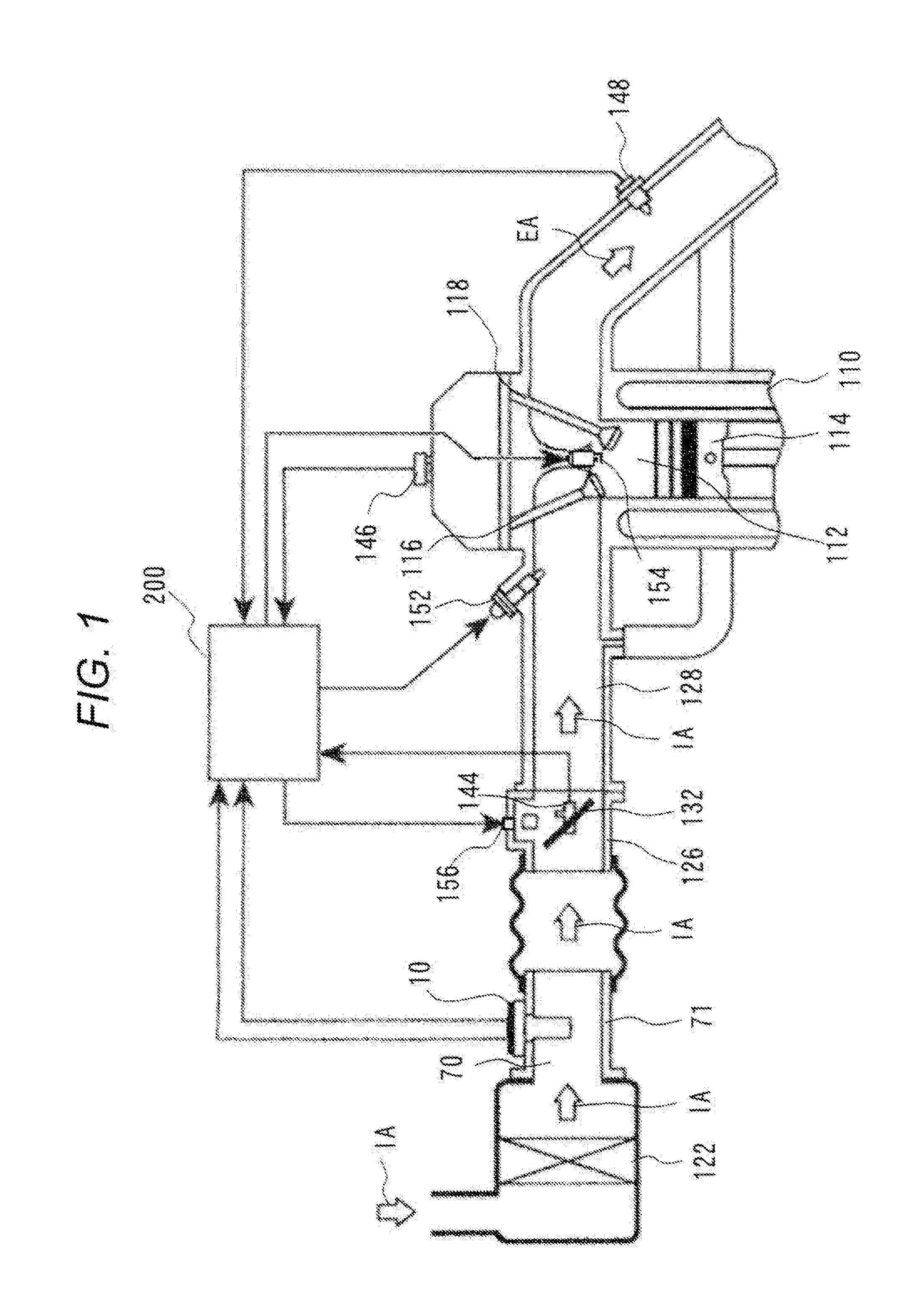
[0025]FIG. 1 is a systematic view illustrating an embodiment of an internal-combustion engine control system of an electronic fuel injection type, using a thermal flowmeter according to the present embodiment. As illustrated in FIG. 1, based on operation of an internal-combustion engine 110 including an engine cylinder 112 and an engine piston 114, intake air is taken as a gas IA to be measured from an air cleaner 122, and introduced to a co...


PUM


Abstract

Provided is a physical quantity measuring device for reducing the influence of heat, other than the heat of a gas to be measured, on a measuring unit for measuring a physical quantity of the gas to be measured. The physical quantity measuring device according to the present invention includes a chip package 40 and a casing 11. The chip package 40 is molded from a polymeric resin, including first and second measuring units measuring first and second physical quantities of the gas to be measured, and a signal processing unit being connected to the first and second measuring units, and processing signals transmitted from the first and second measuring units, The casing 11 fixedly stores the chip package 40, and includes first and second bypass passages 12 and 14 allowing the gas to be measured taken from a main passage 70, to flow in the first measuring unit. In the chip package 40, the signal processing unit 44 is disposed between the first and second measuring units. In the casing 11, a cooling unit is formed for allowing the gas to be measured from the main passage 70 to flow between the first measuring unit and the second measuring unit, and cooling the signal processing unit 44.

Description

TECHNICAL FIELD[0001]The present invention relates to a physical Quantity measuring device preferably measuring a physical quantity of a gas to be measured.BACKGROUND ART[0002]There has been a physical quantity measuring device including a measuring unit for measuring a physical quantity, such as the flow rate, the pressure, the tenmerature, or the humidity of ages to be measured. For example, the measuring unit for measuring a physical quantity includes a flow measuring device including a flow measuring element. The flow measuring element includes a thermal, flow measuring element, and the thermal, flow measuring element is a sensor having a heater element and a thermopile element formed on a silicon substrate, and measuring the flow rate in a measuring unit based on transfer of heat of the heater element.[0003]The flow sensor can measure a wide flow range, has a relatively good accuracy, and is inexpensive, so that the flow sensor is widely used for consumer measuring instruments ...

Claims


Application Information

Patent Timeline
IPC IPC(8): G01F1/684G01F15/14
CPCG01F15/14G01F1/684G01F1/6845
Inventor ISOYA, YUKIHOSHIKA, HIROAKIYOGO, TAKAYUKIMIKI, TAKAHIRO
Owner HITACHI ASTEMO LTD
Why Eureka
Try Eureka