High power handling polarization switches

a polarization switch and high power technology, applied in the field of displays, can solve problems such as degraded performance and localized heating, and achieve the effect of high irradian

Active Publication Date: 2016-05-26
REAID INC
View PDF2 Cites 1 Cited by
  • Summary
  • Abstract
  • Description
  • Claims
  • Application Information

AI Technical Summary

Benefits of technology

[0010]These and other advantages and features of the present disclosure will become apparent to those of ordinary skill in the art upon reading this disclosure in its entirety.

Problems solved by technology

This energy is dissipated in the optical assembly, resulting in localized heating.
Localized heating in such an assembly causes a distribution in strain, usually resulting in significant birefringence that degrades performance.

Method used


Image

  • High power handling polarization switches
  • High power handling polarization switches
  • High power handling polarization switches

Examples


Embodiment Construction

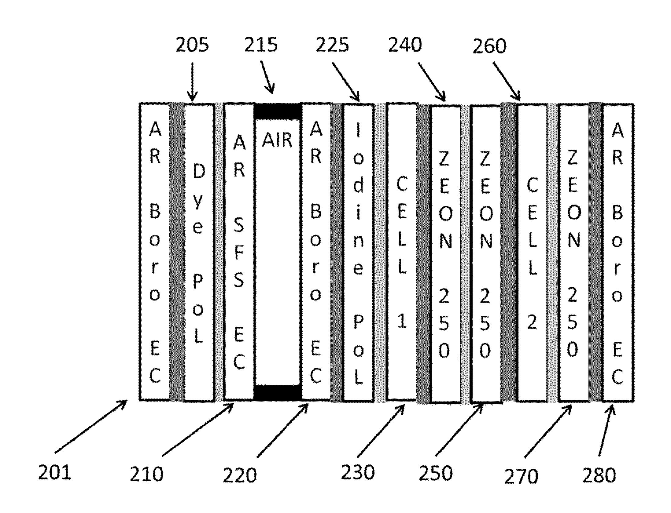
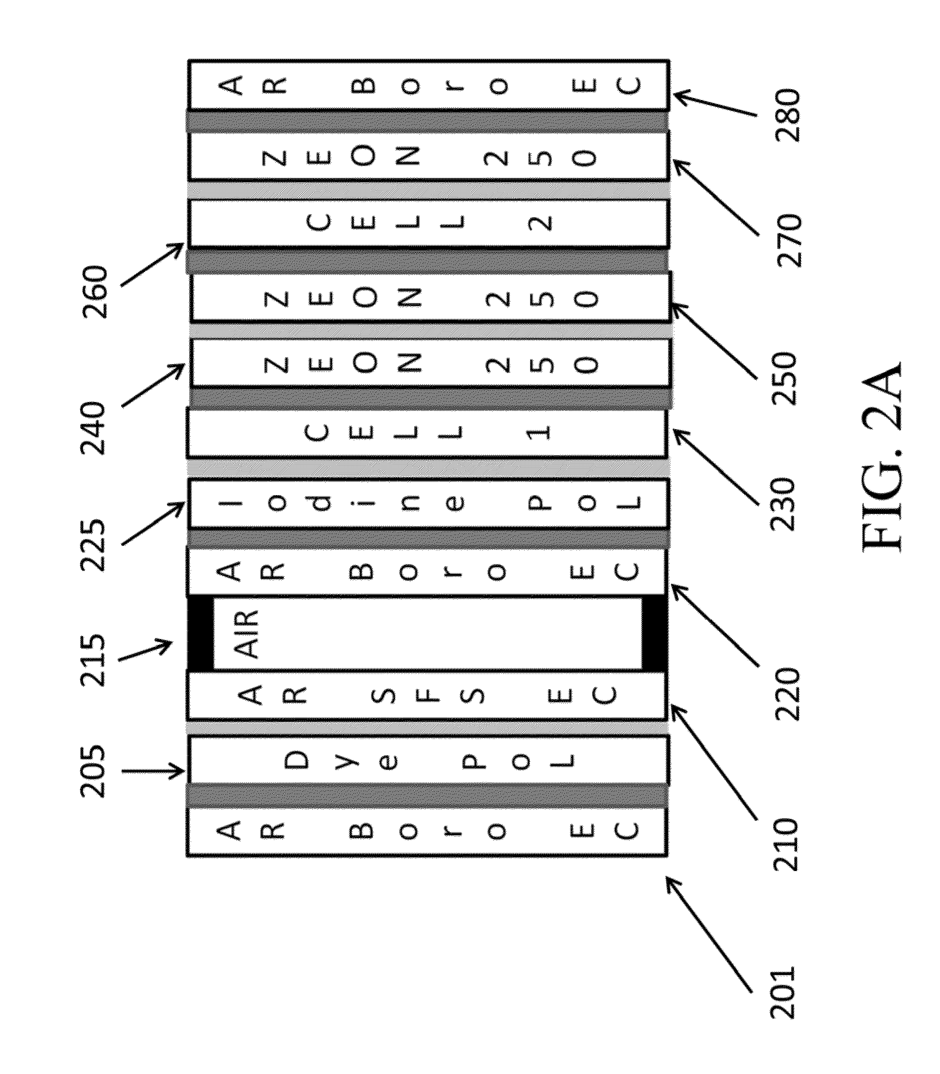
[0016]Polarization switches are frequently used to temporally encode stereoscopic imagery for single-projector 3D projection display. An example is the ZScreen, which may include a neutral linear input polarizer, followed by alternately engaged liquid crystal pi-cells. As the output from many projector models is substantially unpolarized, such as those based on the Texas Instruments DLP microdisplay, more than half of the energy is absorbed by the input polarizer of the polarization switch, This energy is dissipated in the optical assembly, resulting in localized heating. The polarization switch is usually assembled using optical adhesives to eliminated air-glass interfaces that produce light loss and degradation in performance, for example, contrast and transmitted wavefront distortion. Localized heating in such an assembly causes a distribution in strain, usually resulting in significant birefringence that degrades performance. In 3D display, this is manifested as a loss in the st...


PUM

PropertyMeasurementUnit
thicknessaaaaaaaaaa
thicknessaaaaaaaaaa
thickaaaaaaaaaa

Abstract

Liquid crystal devices are described that maintain performance of polarization / amplitude modulation under high irradiance conditions. Configurations that isolate polarizing elements under high thermal load are discussed which allow other elements, such as glass, which may be sensitive to stress birefringence to remain near optimum thermal conditions.

Description

CROSS-REFERENCE TO RELATED APPLICATIONS[0001]This application is related to U.S. patent application Ser. No. 12 / 156,683, “Display device,” tiled Jun. 4, 2008 (Attorney Ref No. 95194936.093001), U.S. patent application Ser. No. 12 / 853,286, “Stereoscopic flat panel display with synchronized backlight, polarization control panel, and liquid crystal display,” filed Aug. 9, 2010 (Attorney Ref. No. 95194936.093101), U.S. patent application Ser. No. 12 / 853,274, “Stereoscopic flat panel display with updated blanking intervals, filed Aug. 9, 2010, (Attorney Ref No. 9519.4936.266001), U.S. patent application Ser. No. 12 / 853,279. “Stereoscopic flat panel display with scrolling backlight and synchronized liquid crystal display update,” filed Aug. 9, 2010, (Attorney Ref. No. 95194936.266101), U.S. patent application Ser. No. 12 / 853,265, “Stereoscopic flat panel display with a continuously lit backlight,” filed Aug. 9, 2010, (Attorney Ref. No. 95194936.266201), and U.S. patent application Ser. No...

Claims


Application Information

Patent Timeline
Patent Type & Authority Applications(United States)
IPC IPC(8): G02B27/26G02B30/25
CPCG02B27/26G02F1/0136G02F1/13471G02F1/13306G02F1/133382G02F1/133385G02F2201/36G02F2201/38G02B27/283H04N13/337H04N13/341G02F1/133528G02B30/25G02F1/133634
Inventor SHARP, GARY D.GILMAN, SCOTTCOLEMAN, DAVID A.
Owner REAID INC
Why Eureka
Try Eureka