

Low voltage differential signaling (LVDS) driving circuit
a driving circuit and low voltage technology, applied in logic circuits, oscillation generators, pulse techniques, etc., can solve the problems of insufficient head room of current sources and limited output range of differential signaling circuits
- Summary
- Abstract
- Description
- Claims
- Application Information
AI Technical Summary
Benefits of technology
Problems solved by technology
Method used
Image

Examples
Embodiment Construction
[0030]In order to illustrate the purposes, features and advantages of the invention, the embodiments and figures of the invention are described in detail as follows.
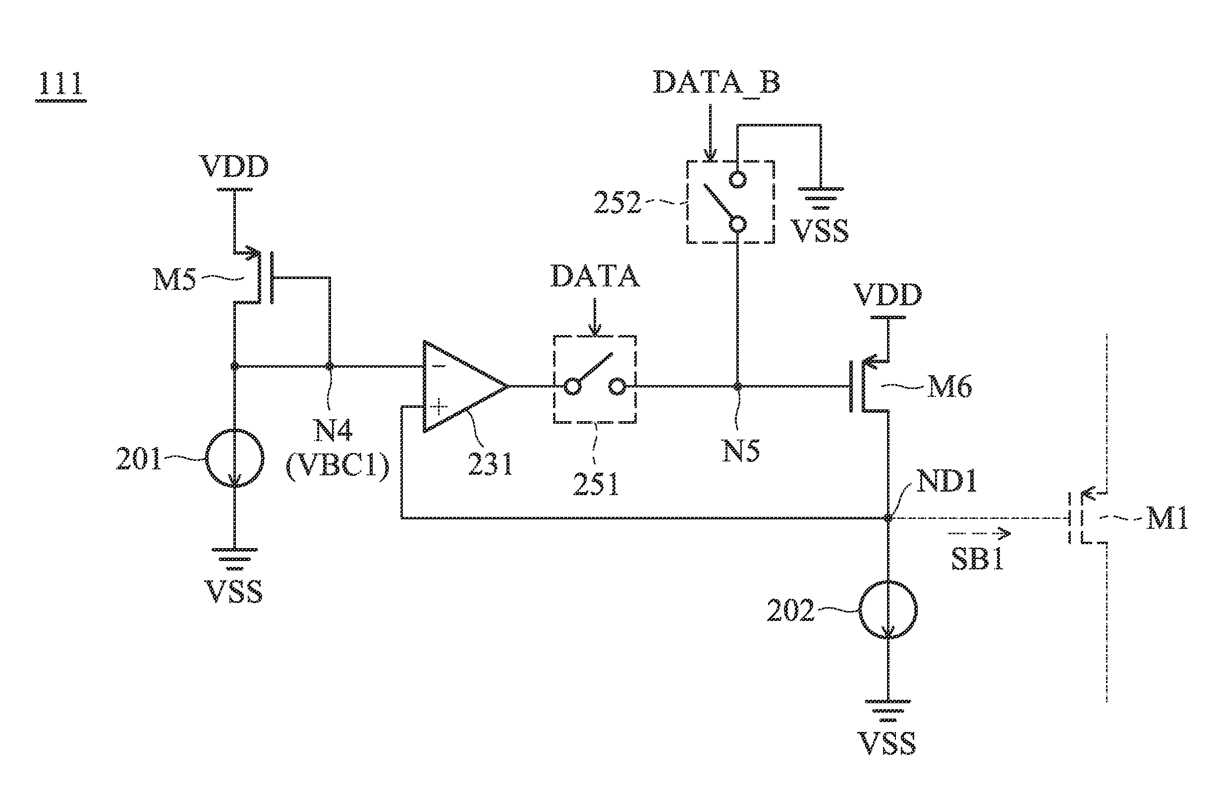
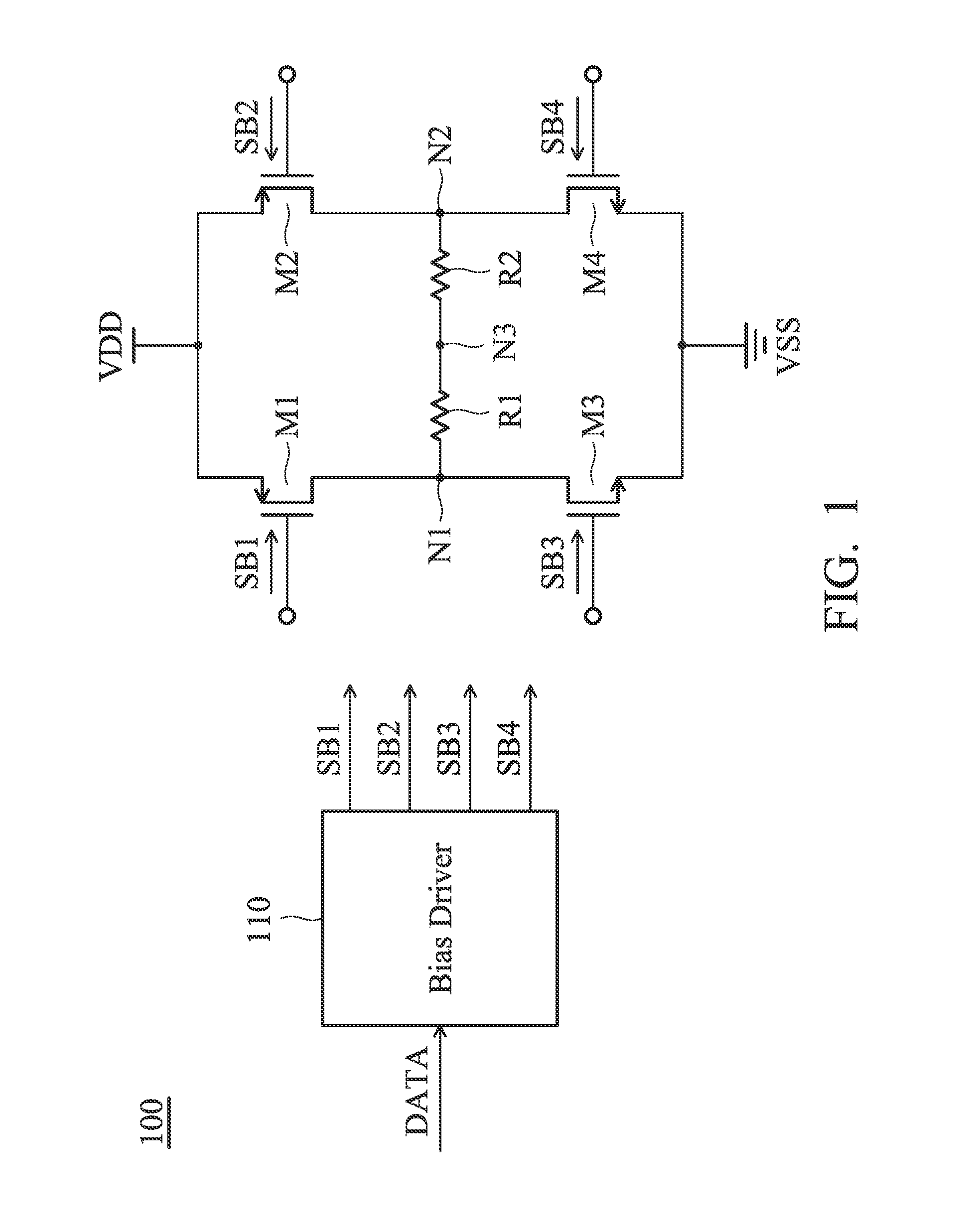
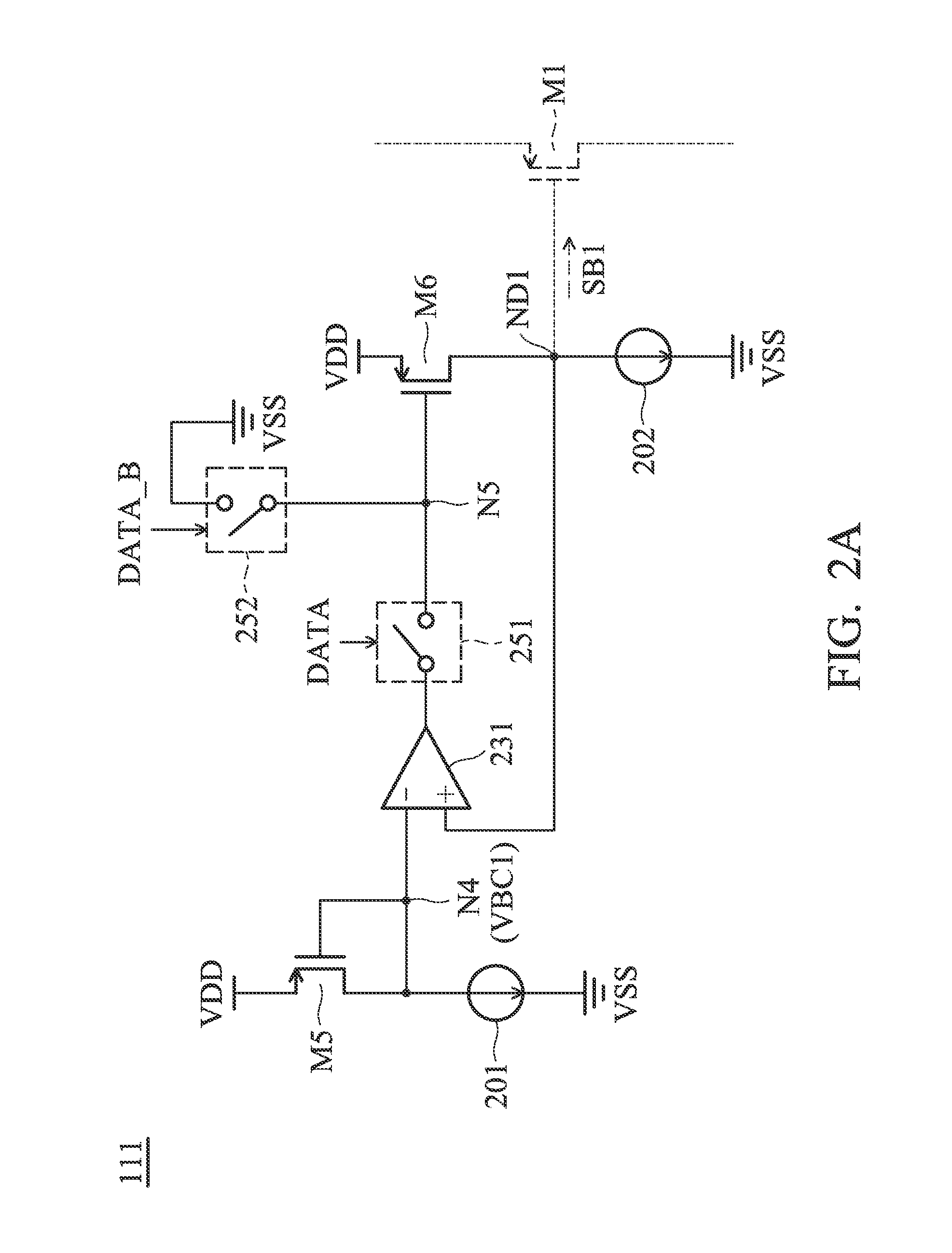
[0031]FIG. 1 is a diagram of an LVDS (Low Voltage Differential Signaling) driving circuit 100 according to an embodiment of the invention. The LVDS driving circuit 100 includes a first transistor M1, a second transistor M2, a third transistor M3, a fourth transistor M4, a first resistor R1, a second resistor R2, and a bias driver 110. The bias driver 110 generates a first bias signal SB1, a second bias signal SB2, a third bias signal SB3, and a fourth bias signal SB4 for controlling the first transistor M1, the second transistor M2, the third transistor M3, and the fourth transistor M4, respectively, according to a data signal DATA. The data signal DATA may be a digital signal. In some embodiments, the first transistor M1 and the second transistor M2 are PMOS transistors (P-type Metal Oxide Semiconductor Field Effect Tra...
PUM
 Abstract
Description
Claims
Application Information