An aerodynamic lifting device

Active Publication Date: 2016-06-02
ENTECHO (PTY) LTD
View PDF97 Cites 6 Cited by
  • Summary
  • Abstract
  • Description
  • Claims
  • Application Information

AI Technical Summary

Benefits of technology

The present invention provides an aerodynamic lifting device with a better way to transmit torque to the rotor that reduces the weight and complexity of the device, and also reduces the risks of failure from high loads. This makes it easier to operate and maintain.

Problems solved by technology

This defines a technical challenge because increasing the volume of air generally involves an increase in the size of the craft as evidenced in the large diameter, high speed blades used in helicopters.
Torque transmission to drive the rotor of the aerodynamic lifting device raises a number of challenges.
This roller arrangement is complex to compensate for gyroscopic forces.
Premature failure is therefore a risk and, in any event, undesirable weight and complexity is added to the device.

Method used


Image

  • An aerodynamic lifting device
  • An aerodynamic lifting device
  • An aerodynamic lifting device

Examples


Embodiment Construction

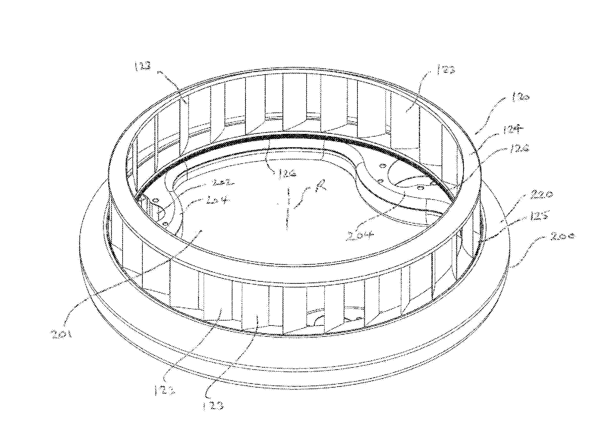
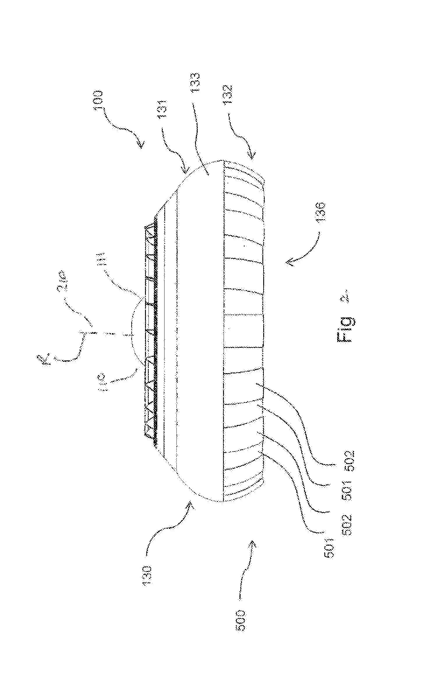
[0048]FIG. 2 shows an airborne craft 100 developed by the applicant and intended to be used in a wide variety of applications. The craft 100 is approximately 2.4 metres wide and comprises a central load carrying space 110 that provides a cockpit operating area 111 for an operator (not shown) while maximizing the area available for fluid flow, that is airflow, by a radial drum fan having a rotor 120 as shown in other drawings. The air flow to the rotor 120 flows past the central area of the craft (that is, through the central load carrying space 110) and is expelled radially by the drum rotor fan 120. The radial airflow is re-directed to generate downwards thrust by flexible shroud 130.

[0049]Operation of rotor 120 and deflection of air flow by shroud 130 to direct thrust is described in detail in U.S. Pat. Nos. 7,556,218, 8,181,902 and 8,646,721, the contents of which have been incorporated herein by reference.

[0050]The shroud 130 of the craft 100 in FIG. 1 creates a generally downwa...


PUM


Abstract

An aerodynamic lifting device comprises a chassis (200); a rotor (120) having a rotational axis (R) and a plurality of rotor blades (123) disposed in an annular ring about the rotational axis (R) supported by the chassis (200); and a torque transmission means (126,130,139) to provide tractive force for rotating the rotor (120). The torque transmission means (126,130,139) co-operates with at least one complementary and circumferentially extending drive surface (126a, 126b) of the rotor (120) to transmit tractive force as tangential forces and resultant torque sufficient to drive the rotor (120) and thereby generate lift. The aerodynamic lifting device may be used in airborne craft which may be deployed for waterborne use with a buoyant chassis (200), especially of toroidal shape, for elevating the rotor (120) above a water surface (300) during take off and landing.

Description

FIELD OF THE INVENTION[0001]This invention relates to an aerodynamic lifting device for airborne craft, particularly those with a thrust control or thrust vectoring shroud. The invention is also particularly useful in aerodynamic lifting devices using drum rotor type fans for thrust generation and airborne craft incorporating such devices.BACKGROUND TO THE INVENTION[0002]Powered airborne craft, manned and unmanned, may be capable of hovering in a stationary position while airborne. Such aircraft may range from craft which operate close to the ground relying on a cushion of air to those capable of free flight and vertical takeoff and landing. Craft operating close to the ground may be designed for transportation and recreational use whereas the free flight craft may operate at generally low altitudes compared to commercial aircraft and may be considered for applications including airport-to-downtown shuttle, tourism applications, home-to-office commuting, search and rescue and survei...

Claims


Application Information

Patent Timeline
IPC IPC(8): B64C39/06
CPCB64C39/064A63H27/12B60V1/046B60V3/06
Inventor SCHLUNKE, KIM CHRISTOPHERSEEBER, KENLAMB, RODNEY
Owner ENTECHO (PTY) LTD
Why Eureka
Try Eureka