Thermal management system for vehicles

a technology for managing systems and vehicles, applied in the direction of machines/engines, mechanical equipment, transportation and packaging, etc., can solve the problems of complicated circuit configuration, complicated structure, and complicated circuit configuration

Active Publication Date: 2016-06-02
DENSO CORP
View PDF0 Cites 61 Cited by
  • Summary
  • Abstract
  • Description
  • Claims
  • Application Information

AI Technical Summary

Benefits of technology

[0009]The inventors of the present application have found through their studies that the related-art cooling system, which is designed to cool a plurality of devices, including a motor generator, an inverter, and a battery, advantageously needs only one exterior heat exchanger. However, the cooling system might lead to a more complicated circuit configuration as a whole. In particular, as the number of devices increases, the entire circuit configuration tends to be more complicated.
[0011]To appropriately cool the respective devices, the coolant to circulate through the respective devices is proposed to be switchable among the devices, which leads to an increase in the number of circulation circuits according to the number of devices. Together with the increase, the number of valves that connect and disconnect between the cooling circuit and the respective circulation circuits is also increased, which results in a very complicated structure for a flow path that connects each circulation circuit to the cooling circuit.
[0013]As described in the previous application example, the devices are connected in parallel between first and second switching valves that are designed to switch the flow of heat media. With such a simple structure, the heat media circulating through the devices can be switched among the devices.

Problems solved by technology

However, the cooling system might lead to a more complicated circuit configuration as a whole.
In particular, as the number of devices increases, the entire circuit configuration tends to be more complicated.
Together with the increase, the number of valves that connect and disconnect between the cooling circuit and the respective circulation circuits is also increased, which results in a very complicated structure for a flow path that connects each circulation circuit to the cooling circuit.

Method used


Image

  • Thermal management system for vehicles
  • Thermal management system for vehicles
  • Thermal management system for vehicles

Examples


first embodiment

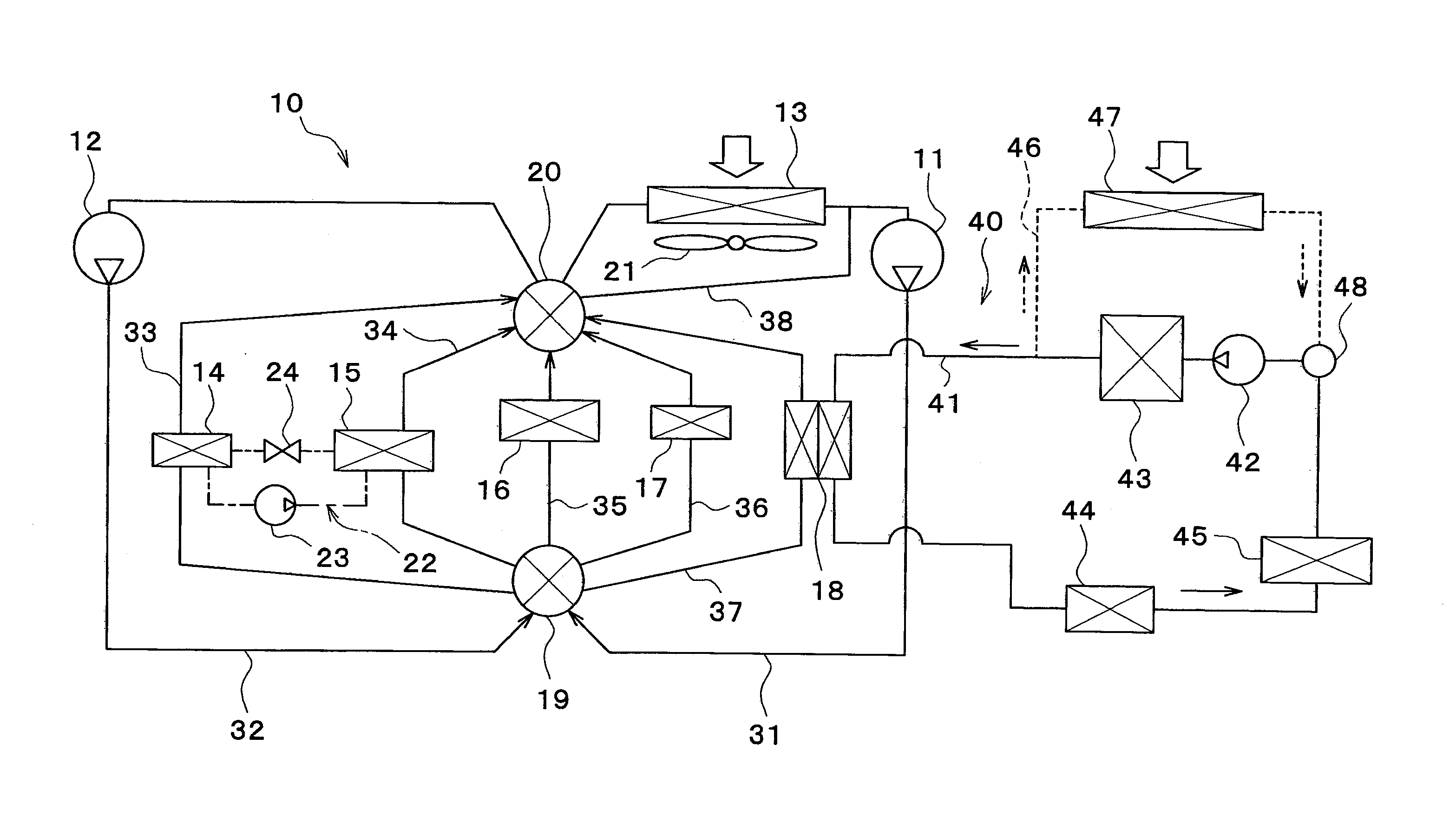
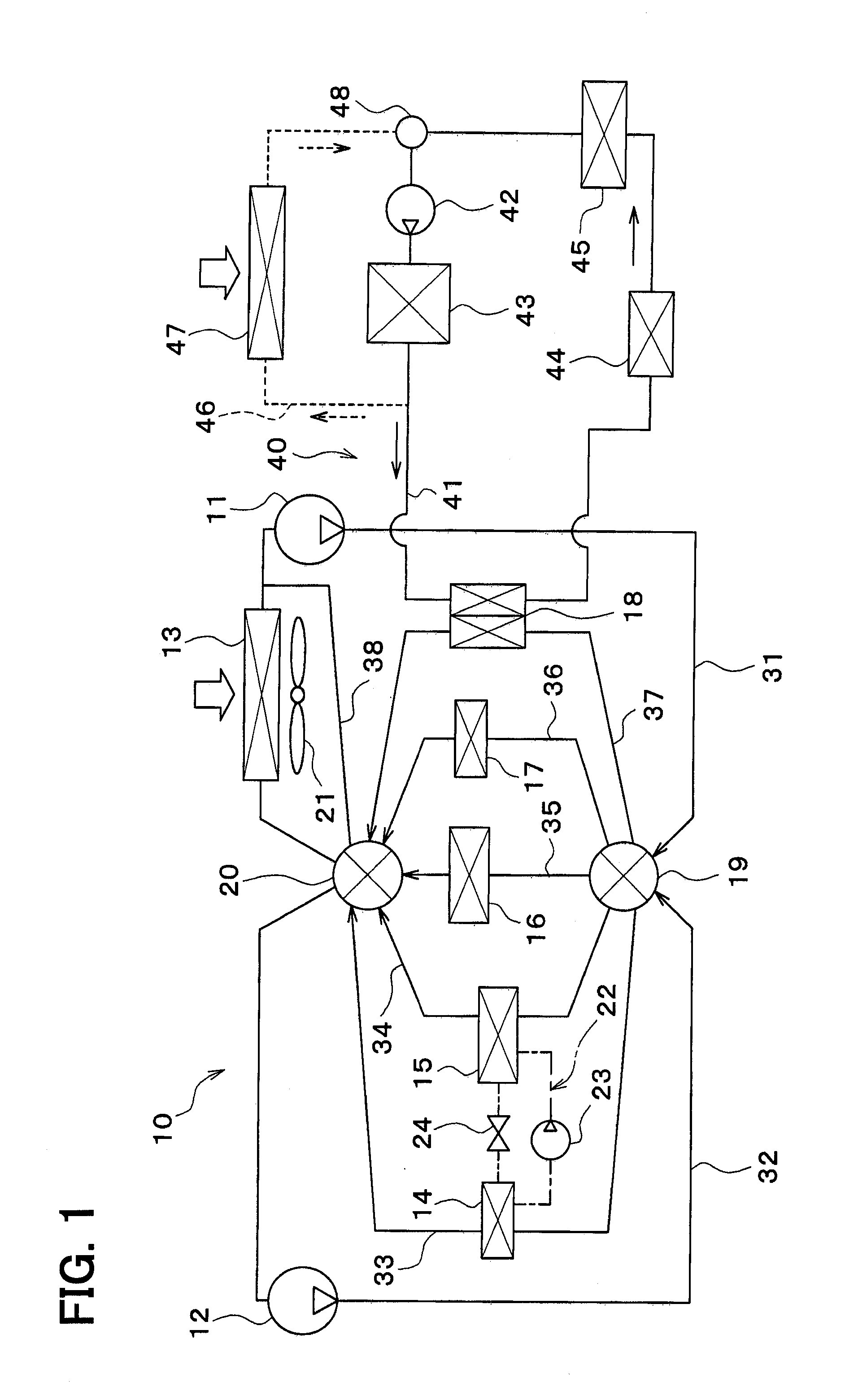
[0041]In the following, a first embodiment of the present disclosure will be described based on FIGS. 1 to 9. A vehicle thermal management system 10 shown in FIG. 1 is used to adjust the temperature of various devices mounted on a vehicle or an interior of the vehicle to an appropriate level.

[0042]In this embodiment, the thermal management system 10 is applied to a hybrid vehicle that can obtain the driving force for traveling from both an engine (internal combustion engine) and an electric motor for traveling.

[0043]The hybrid vehicle of this embodiment is configured as a plug-in hybrid vehicle that can charge the battery (vehicle-mounted battery) mounted on the vehicle, with power supplied from an external power source (commercial power source) during stopping of the vehicle. For example, a lithium ion battery can be used as the battery.

[0044]A driving force output from an engine is used not only for traveling of the vehicle, but also for operating a generator. Power generated by t...

second embodiment

[0173]In a second embodiment of the present disclosure, as shown in FIG. 10, instead of the intake air cooler 16, a battery cooler 70 and an inverter motor cooler 71 are provided with respect to the arrangement of the above-mentioned first embodiment.

[0174]The battery cooler 70 has a flow passage for coolant, and cools the battery by dissipating the heat from the battery into the coolant. The battery preferably has its temperature maintained in a range of about 10 to 40° C. for the purpose of preventing the reduction in output and charging efficiency, the degradation thereof, and the like.

[0175]The inverter motor cooler 71 has a flow passage for coolant, and cools an inverter and / or the traveling electric motor by applying the heat from the inverter and / or the traveling electric motor to the coolant. The inverter is a power converter that converts a direct-current (DC) power supplied from the battery to an alternating-current (AC) voltage to output the AC voltage to the traveling el...

third embodiment

[0301]In the third embodiment, as shown in FIG. 16, with respect to the arrangement of the first embodiment, the arrangement of the radiator 13, the coolant cooler 14, and the coolant heater 15 is modified, and the battery cooler 70, the inverter motor cooler 71, an engine bypass flow path 80, an engine sub-pump 81, and a three-way valve 82 are added.

[0302]The radiator 13 is disposed in a radiator flow path 83. The coolant cooler 14 is disposed on the coolant discharge side of the second pump 12 in the second-pump flow path 32. The coolant heater 15 is disposed on the coolant discharge side of the first pump 11 in the first-pump flow path 31.

[0303]The battery cooler 70 is disposed in the battery cooler flow path 72. The inverter motor cooler 71 is disposed on the downstream side of the coolant flow of the battery cooler 70 in the battery cooler flow path 72.

[0304]The engine bypass flow path 80 is a flow path that allows the engine coolant flowing out of the coolant-coolant heat exch...


PUM


Abstract

A vehicle thermal management system includes a heat medium-heat medium heat exchanger that exchanges heat between a first heat medium drawn into and discharged from a first pump and a second pump, and a second heat medium circulating through an engine cooling circuit. A first switching valve switches between a state in which the first heat medium discharged from the first pump flows, and another state in which the first heat medium discharged from the second pump flows, with respect to the plurality of devices and the heat medium-heat medium heat exchanger. The second switching valve switches between a state in which the first heat medium flows into the first pump, and another state in which the first heat medium flows into the second pump, with respect to the plurality of devices and the heat medium-heat medium heat exchanger.

Description

CROSS REFERENCE TO RELATED APPLICATION[0001]This application is based on a Japanese Patent Application 2013-56099 filed on Mar. 19, 2013, the contents of which are incorporated herein by reference in its entirety.FIELD OF THE INVENTION[0002]The preset disclosure relates to a thermal management system for a vehicle.BACKGROUND ART[0003]Conventionally, for example, as disclosed in Patent Document 1, a heat controller has been proposed which cools a motor generator, an inverter, a battery, and a vehicle compartment of an electric vehicle.[0004]The heat controller in the related art includes a cooling circuit that allows for circulation of a coolant for cooling the motor generator and the inverter, a first circulation circuit that allows for circulation of a coolant for cooling the battery and the vehicle compartment, and a second circulation circuit that allows for circulation of a coolant passing through an exterior heat exchanger and exchanging heat with outside air.[0005]Further, the...

Claims


Application Information

Patent Timeline
Patent Type & Authority Applications(United States)
IPC IPC(8): F01P3/20B60H1/22
CPCB60H1/22F01P3/20F01P2060/045F01P2060/08B60H1/00885B60K11/02B60W10/30B60H1/00278B60H2001/00307B60H1/3228B60H1/32284Y02T10/62B60K6/22B60W20/00
Inventor KAKEHASHI, NOBUHARUKATOH, YOSHIKIENOMOTO, NORIHIKONISHIKAWA, MICHIOSUGIMURA, KENGO
Owner DENSO CORP
Why Eureka
Try Eureka