Hydrostatic variator

a technology of variator and hydraulic pump, which is applied in the direction of rotary clutches, fluid couplings, gearing, etc., can solve the problems of reducing the efficiency of the hydraulic drive system, reducing the efficiency of the pump, and requiring multiple servos, so as to improve the efficiency

Active Publication Date: 2016-06-02
PARKER HANNIFIN CORP +1
View PDF5 Cites 1 Cited by
  • Summary
  • Abstract
  • Description
  • Claims
  • Application Information

AI Technical Summary

Benefits of technology

[0002]Although many promising alternative power sources are being developed for motor vehicles, the predominant power source today is the internal combustion engine. Current IC-driven designs have evolved substantially over the last century but there is still room for improvement. The use of continuously variable and infinitely variable transmissions (CVTs and IVTs) allows the engine to operate at its peak performance point improving performance as well as efficiency while reducing the impact on the environment.
[0004]Several different devices such as toroidal drives to electric motor / generator sets have been used to create a continuously variable gearset or “variator” for the IVT. Hydrostatic variators are currently the best suited of these to handle the power demands of large on and off road trucks and construction equipment. In addition, mobile hydraulics technology is very mature offering proven reliability as well a wide range of readily available components.
[0008]The variator of a split path IVT must be designed to handle as much as or more than half of the input power to the transmission. However, depending on the loading cycle of the vehicle, full power may not be required all the time. A hydraulic drive system which is “too large” for the amount of power being transferred will not run as efficiently as a smaller system. A method commonly employed to improve this efficiency under partially loaded conditions is to reduce the pump and motor displacement proportionately (i.e. reducing system size) to increase system pressure while maintaining the desired speed ratio.
[0012]A hydrostatic variator providing dynamic adjustment of system size in a common yoke design comprises a housing, first and second bent axis piston drive units which each comprise a rotating group, a yoke common to both drive units, and a yoke servo assembly to position the yoke relative to the housing. The respective rotating groups in each piston drive unit are arranged to rotate within a yoke. And the yoke includes one or more fluid channels for fluid communication between the first and second bent axis piston drive units. The yoke is rotatable relative to the housing about a yoke axis perpendicular to both a drive shaft of the first bent axis piston drive unit and to a drive shaft of the second bent axis piston drive unit to simultaneously alter an angle between the drive shaft axis and the rotating group axis of each of the first and second bent axis piston drive units. For purposes of dynamic adjustment, the rotating group of the first bent axis piston drive unit is arranged to be movable relative to the yoke in order to alter the angle between the drive shaft axis and the rotating group axis of the first bent axis piston drive unit independent of the second bent axis piston drive unit. Since the system size can be varied, efficiency can be improved for conditions other than the maximum design torque of the variator.
[0014]In another embodiment, the rotating group of the second bent axis piston drive unit can be arranged, or also be arranged, to be movable relative to the yoke to alter the angle between the drive shaft axis and the rotating group axis of the second bent axis piston drive unit independent of the first bent axis piston drive unit. With adjustment capability for both rotating groups, the possible range of adjustment of system size of the variator can be increased.

Problems solved by technology

A hydraulic drive system which is “too large” for the amount of power being transferred will not run as efficiently as a smaller system.
Problems arise when multiple servos are required to respond quickly and in a synchronized manner.
Stick / slip conditions can occur which vary with system pressure; creating a control algorithm to address all situations can be complex and difficult.
In the current state of the art, servo mechanisms have limitations with regards to response to transient forces.
All of this acids a degree of unpredictability to the system.
The problem with this approach is the angle between the pump and motor yokes is fixed, and hence the system size is fixed.
When applied in a split path transmission, potential efficiency gains by altering system size are not possible.

Method used


Image

  • Hydrostatic variator
  • Hydrostatic variator
  • Hydrostatic variator

Examples


Embodiment Construction

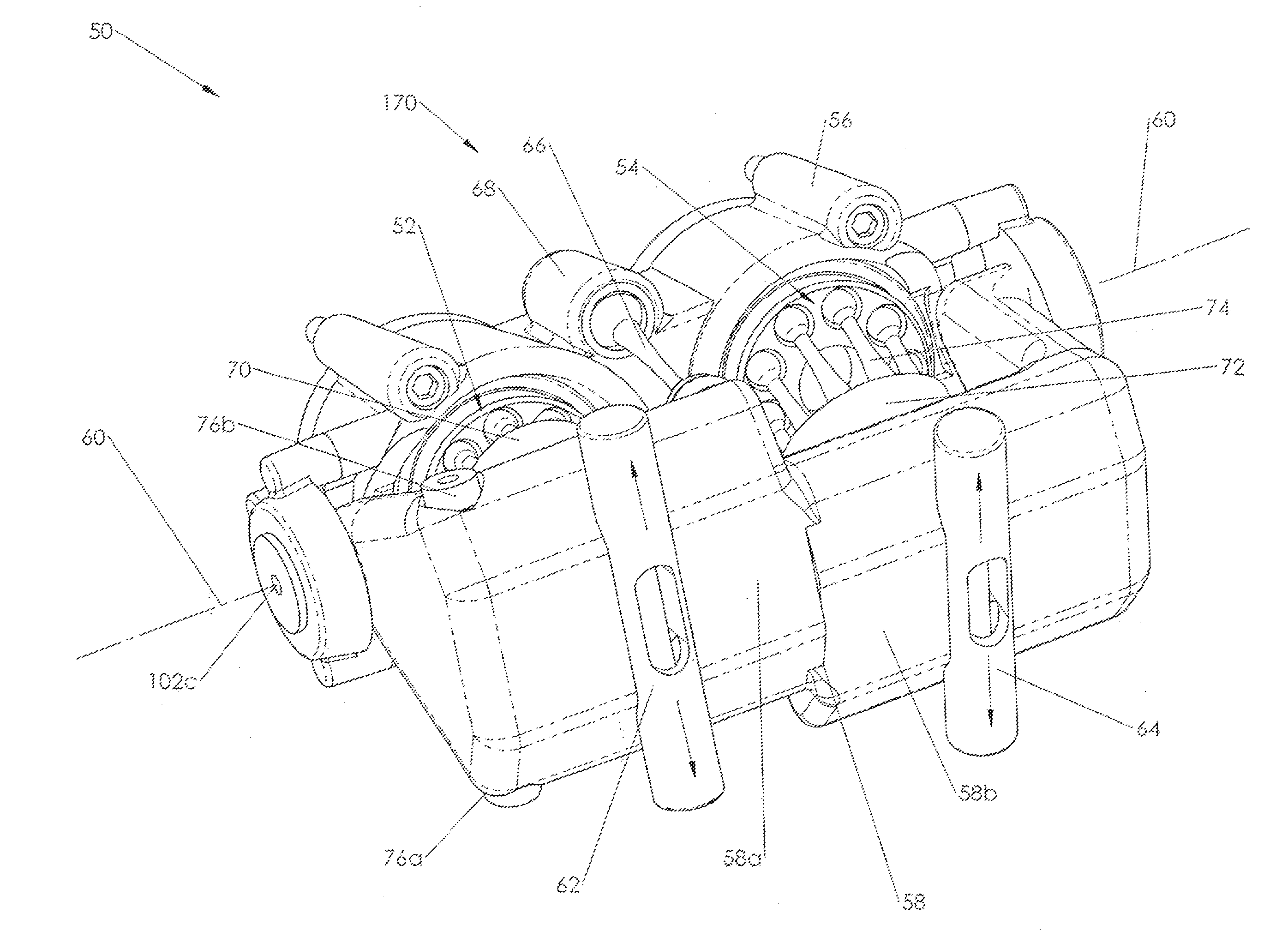
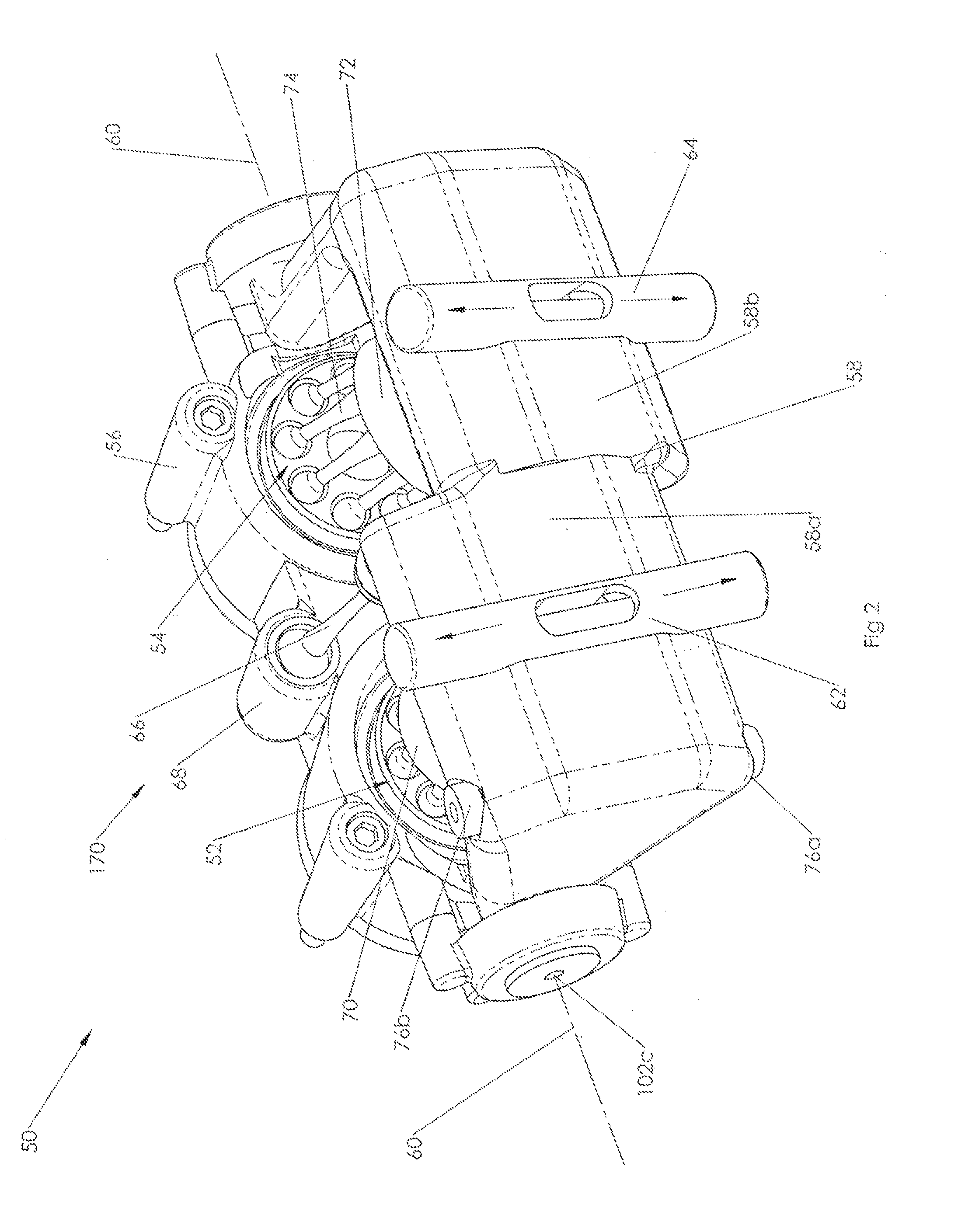
[0030]As is commonly used in the art, herein “system size” refers to the sum of the pump and motor displacements in a hydrostatic variator.

[0031]FIG. 2 illustrates a perspective view of a hydrostatic variator or hydraulic module 50 according to an embodiment of the invention. Hydrostatic variator 50 comprises a housing 56 that supports first bent axis piston drive unit 52, shown on the left hand side of the figure and second bent axis piston drive unit 54 shown on the right hand side of the figure. Housing 56 supports a distal end of each of the bent axis piston drive units 52, 54 and allows each of the bent axis piston drive units 52, 54 to rotate relative to the housing 56. Housing 56 is manufactured such that output shafts (not shown in the figure) of each of the bent axis piston drive units 52, 54 are parallel to one another and are generally perpendicular to the housing. Each of the bent axis piston drive units 52, 54 includes at least two pistons 74 (in this example, nine pist...


PUM


Abstract

A hydrostatic variator having a common yoke design and two or more bent axis piston drive units is disclosed in which the rotating group of a drive unit is arranged to be movable relative to the yoke to alter the angle between its drive shaft axis and rotating group axis independent of the other drive unit. This can be accomplished using movable sector plates coupled to the rotating groups that are arcuately movable within the yoke about the axis perpendicular to the respective drive shaft axes of the drive units. Such variators enjoy the response and packaging advantages of a common yoke design while still allowing dynamic adjustment of system size. In turn, varying system size allows for efficiency to be improved at conditions other than at the maximum design torque.

Description

INTRODUCTION[0001]The present invention relates generally to a hydrostatic variator.[0002]Although many promising alternative power sources are being developed for motor vehicles, the predominant power source today is the internal combustion engine. Current IC-driven designs have evolved substantially over the last century but there is still room for improvement. The use of continuously variable and infinitely variable transmissions (CVTs and IVTs) allows the engine to operate at its peak performance point improving performance as well as efficiency while reducing the impact on the environment.[0003]In a split path IVT, power from the engine is split into two branches and recombined at the output. One branch is purely mechanical and may consist of as little as a shaft and a pair of gears. The other branch consists of a continuously variable device able to change the speed and torque ratios of the transmission. Power will flow exclusively through the mechanical branch, through the va...

Claims


Application Information

Patent Timeline
Patent Type & Authority Applications(United States)
IPC IPC(8): F16H39/16
CPCF16H39/16F16H61/423F16H61/433F16H39/20F16H39/14
Inventor CZEPAK, JOHNDYCK, GERALDVALLEBRANT, PER-OLA
Owner PARKER HANNIFIN CORP
Why Eureka
Try Eureka