
Prism sheet and liquid crystal display device having the same

a technology of liquid crystal display device and prism, which is applied in the field of prism, to achieve the effect of improving optical efficiency

Active Publication Date: 2016-06-02
LG DISPLAY CO LTD
View PDF9 Cites 8 Cited by
  • Summary
  • Abstract
  • Description
  • Claims
  • Application Information

AI Technical Summary

Benefits of technology

The patent describes a prism sheet and its use in a liquid crystal display (LCD) device. The prism sheet has a unique bottom surface that improves optical efficiency by changing the refractive angle of light incident at an angle less than a minimum angle into an effective angle. This results in increased power collection efficiency and reduced power consumption, while also reducing manufacturing costs as a light source of low intensity can be used. Overall, the use of the prism sheet in the LCD device improves optical efficiency and provides better performance.

Problems solved by technology

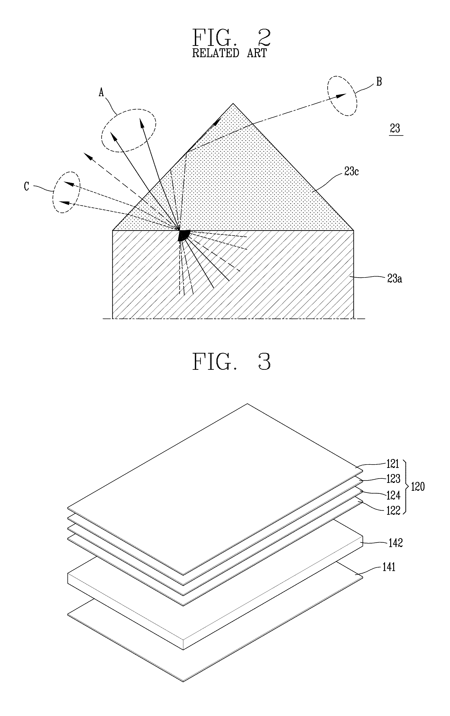
In addition, although part of the light is recycled by total reflection, the light incident at an angle more than or less than a certain angle is refracted toward an invalid area (region ‘B or C’) and is thus lost.

Method used


Image

  • Prism sheet and liquid crystal display device having the same
  • Prism sheet and liquid crystal display device having the same
  • Prism sheet and liquid crystal display device having the same

Examples


first embodiment

[0075]FIG. 3 is an exemplary exploded perspective view showing a structure of a backlight according to the present disclosure.

[0076]FIG. 3 shows an example of an edge type backlight having a light source located at one side of the liquid crystal panel, but the present disclosure is not limited thereto. The present disclosure is also applicable to a direct type backlight device in which a light source is located on the rear surface of the liquid crystal panel.

[0077]Referring to FIG. 3, the backlight according to the present disclosure includes a light guide plate 142 to guide light incident through a side surface of the light guide plate 142 facing a light source toward the liquid crystal panel.

[0078]The backlight may include a reflection sheet 141 disposed on a rear surface of the light guide plate 142, and a plurality of optical sheets 120 disposed on a front surface of the light guide plate 142 to improve efficiency of light transmitted through the light guide plate 142 and to irr...

second embodiment

[0115]The concave surface of the prism pattern may be provided in a groove formed in the base film or the auxiliary resin layer. In this case, loss of incident light that is incident at an angle exceeding a maximum angle may be minimized, which will be described in detail with reference to the present disclosure.

[0116]FIG. 6 is a perspective view schematically showing a prism sheet according to a second embodiment of the present disclosure, and FIG. 7 is a perspective view schematically showing another prism sheet according to a second embodiment of the present disclosure.

[0117]FIG. 6 shows a case of forming the bottom surface of the 2nth prism pattern (where ‘n’ is a natural number) in the groove of the base film, as an example. FIG. 7 shows a case of forming the bottom surface of the 2n-1th prism pattern in the groove of the base film, as an example. FIG. 8 is a sectional view schematically showing a prism sheet according to a second embodiment of the present disclosure.

[0118]Refe...


PUM


Abstract

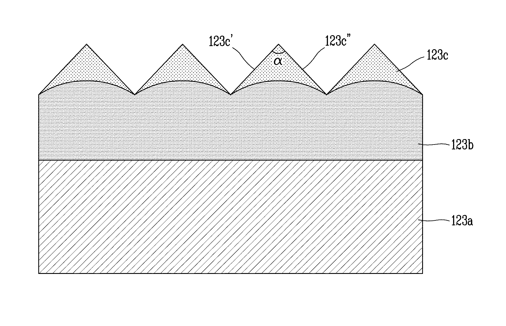
A prism sheet and a liquid crystal display (LCD) device having the same are provided to improve optical efficiency of the prism sheet by changing a refractive angle of light, which is incident at an angle less than a minimum angle to an effective angle, by forming a concave surface on a bottom surface of prism patterns. Optical efficiency of the prism sheet is also improved by refracting light, which is incident at an angle more than a maximum angle, toward the adjacent prism pattern, by forming the bottom surface of the 2nth prism pattern in a groove of a base film.

Description

CROSS-REFERENCE TO RELATED APPLICATION[0001]Pursuant to 35 U.S.C. §119(a), this application claims the benefit of earlier filing date and right of priority to Korean Application No. 10-2014-0170735, filed on Dec. 2, 2014, the contents of which is incorporated by reference herein in its entirety.BACKGROUND[0002]1. Field of the Invention[0003]The present disclosure relates to a prism sheet, and more particularly, to a prism sheet with improved optical efficiency and a liquid crystal display device having the same.[0004]2. Background of the Related Art[0005]Display devices act as visual information output media that provide various types of images to users. Consumers require that display devices meet certain requirements, such as exhibiting low power consumption, having a thin form factor, being lightweight, and being capable of outputting high resolution images.[0006]Display devices may be classified into an emissive type and a transmissive type. The spontaneous light emitting (emissi...

Claims


Application Information

Patent Timeline
IPC IPC(8): G02B5/04F21V5/02G02F1/1335
CPCG02B5/045F21V5/02G02F1/133606G02F1/1335G02F1/133507G02B5/0231G02B6/0053G02F1/133607G02F1/1336G02F1/133615
Inventor KWON, YOONHO
Owner LG DISPLAY CO LTD
Learn More