Display device, module, display system, and electronic device

a display device and module technology, applied in the field of display devices, can solve problems such as and achieve the effect of increasing the power consumption of display devices

Inactive Publication Date: 2016-06-02
SEMICON ENERGY LAB CO LTD
View PDF6 Cites 30 Cited by
  • Summary
  • Abstract
  • Description
  • Claims
  • Application Information

AI Technical Summary

Benefits of technology

[0014]A display device utilizing eyeglasses with shutters displays images for left eye and images for right eye alternately on a screen, which results in an increase in the frequency of image writing to a pixel portion in one frame period as compared with the case of displaying a two-dimensional image. This requires a driver circuit that can be driven at high frequency and also increases the power consumption of the display device.
[0016]Accordingly, it is demanded that a display device can display a two-dimensional image that gives a viewer a strong sense of depth or stereoscopic effect instead of images with binocular parallax such as images for left eye and images for right eye.
[0018]It is an object of one embodiment of the present invention to give a viewer a strong stereoscopic effect or sense of depth in a two-dimensional image. It is another object of one embodiment of the present invention to give a viewer a natural stereoscopic effect or sense of depth in a two-dimensional image.
[0019]It is another object of one embodiment of the present invention to provide a novel display device or display system. It is another object of one embodiment of the present invention to provide a display device or display system with which a viewer can feel a strong stereoscopic effect or sense of depth in a two-dimensional image. It is another object of one embodiment of the present invention to provide a display device or display system with which a viewer can feel a natural stereoscopic effect or sense of depth in a two-dimensional image. It is another object of one embodiment of the present invention to provide a display device or display system with which a viewer can feel a strong stereoscopic effect or sense of depth in a two-dimensional image and is less likely to be fatigued. It is another object of one embodiment of the present invention to provide a display device or display system with which a viewer can feel a natural stereoscopic effect or sense of depth in a two-dimensional image and is less likely to be fatigued.
[0028]According to one embodiment of the present invention, a viewer can feel a strong stereoscopic effect or sense of depth in a two-dimensional image. According to one embodiment of the present invention, a viewer can feel a natural stereoscopic effect or sense of depth in a two-dimensional image.
[0029]According to one embodiment of the present invention, a novel display device or display system can be provided. According to one embodiment of the present invention, a display device or display system with which a viewer can feel a strong stereoscopic effect or sense of depth in a two-dimensional image can be provided. According to one embodiment of the present invention, a display device or display system with which a viewer can feel a natural stereoscopic effect or sense of depth in a two-dimensional image can be provided. According to one embodiment of the present invention, a display device or display system with which a viewer can feel a strong stereoscopic effect or sense of depth in a two-dimensional image and is less likely to be fatigued can be provided. According to one embodiment of the present invention, a display device or display system with which a viewer can feel a natural stereoscopic effect or sense of depth in a two-dimensional image and is less likely to be fatigued can be provided.

Problems solved by technology

This requires a driver circuit that can be driven at high frequency and also increases the power consumption of the display device.

Method used


Image

  • Display device, module, display system, and electronic device
  • Display device, module, display system, and electronic device
  • Display device, module, display system, and electronic device

Examples


embodiment 1

[0060]In this embodiment, a display device and a display system of one embodiment of the present invention will be described with reference to FIGS. 1A1, 1A2, 1B1, 1B2, 1C1, 1C2, 1D1, and 1D2, FIGS. 2A and 2B, FIGS. 3A1, 3A2, and 3B, FIGS. 4A to 4C, and FIGS. 5A and 5B.

[0061]Note that a display device will be described as an example in this embodiment; however, one embodiment of the present invention can also be applied to a light-emitting device and an input / output device. In Embodiment 2 and Embodiment 3, a light-emitting device and an input / output device to which one embodiment of the present invention can be applied will be described.

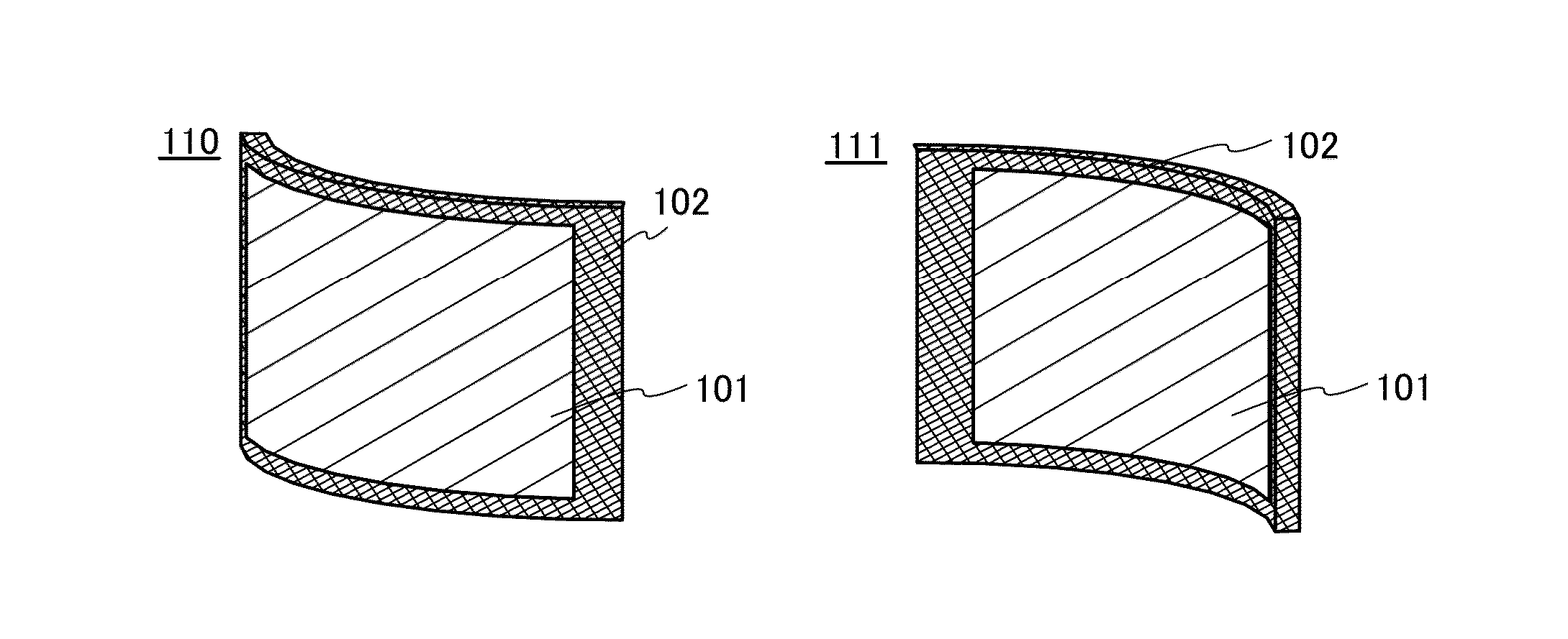
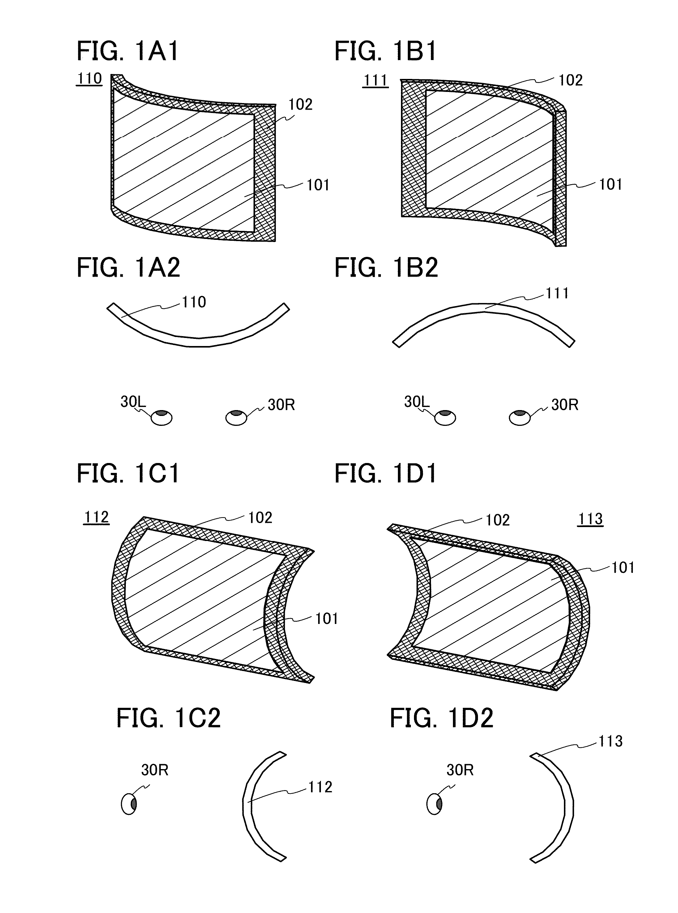
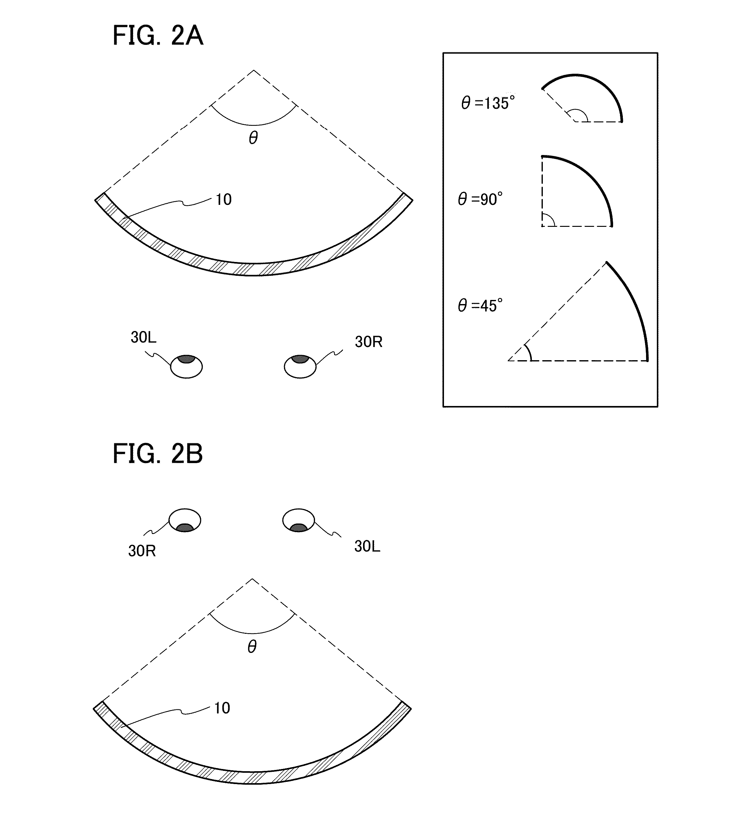
[0062]One embodiment of the present invention is a display device which includes a display portion having a curved surface.

[0063]In some display devices, a phenomenon called natural3D or n3D (both of them are registered trademarks) occurs in which a viewer can feel a natural stereoscopic effect in a two-dimensional image without utilizing binocular ...

embodiment 2

[0143]In this embodiment, a light-emitting device of one embodiment of the present invention will be described with reference to drawings.

[0144]Although a light-emitting device mainly including an organic EL element is described in this embodiment as an example, one embodiment of the present invention is not limited to this example.

[0145]When the light-emitting device described in this embodiment is bent, the minimum radius of curvature of a bent portion of the light-emitting device can be greater than or equal to 1 mm and less than or equal to 150 mm, greater than or equal to 1 mm and less than or equal to 100 mm, greater than or equal to 1 mm and less than or equal to 50 mm, greater than or equal to 1 mm and less than or equal to 10 mm, or greater than or equal to 2 mm and less than or equal to 5 mm. The light-emitting device in this embodiment is free from breakage of an element even when bent with a small radius of curvature (e.g., greater than or equal to 2 mm and less than or ...

specific example 1

[0147]FIG. 6A is a plan view of a light-emitting device, and FIG. 6B is an example of a cross-sectional view taken along dashed-dotted line D1-D2 in FIG. 6A. The light-emitting device in Specific Example 1 is a top-emission light-emitting device using a color filter method. In this embodiment, the light-emitting device can have a structure in which subpixels of three colors of red (R), green (G), and blue (B), for example, express one color; a structure in which subpixels of four colors of R, G, B, and white (W) express one color; a structure in which subpixels of four colors of R, G, B, and yellow (Y) express one color; or the like. There is no particular limitation on color elements, and colors other than R, G, B, W, and Y may be used. For example, cyan or magenta may be used.

[0148]The light-emitting device illustrated in FIG. 6A includes a light-emitting portion 804, a driver circuit portion 806, and an FPC 808.

[0149]The light-emitting device illustrated in FIG. 6B includes a fir...


PUM


Abstract

A display device or a display system with which a viewer can feel a strong or natural stereoscopic effect in a two-dimensional image and is less likely to be fatigued is provided. The display system includes a display portion, a detection portion, and a control portion. The display portion is flexible. The detection portion is configured to detect the conditions of a viewer's eye to obtain detection information and to supply the detection information to the control portion. The control portion is configured to extract information on the viewer's fatigue from the detection information and to change the curvature of the display portion on the basis of the information on the viewer's fatigue. The central angle of the curved surface of the display portion is preferably greater than or equal to 20° and less than 90°.

Description

BACKGROUND OF THE INVENTION[0001]1. Field of the Invention[0002]One embodiment of the present invention relates to a display device, a module, a display system, and an electronic device. In particular, one embodiment of the present invention relates to a display device and a display system utilizing organic electroluminescence (hereinafter also referred to as EL).[0003]Note that one embodiment of the present invention is not limited to the above technical field. Examples of the technical field of one embodiment of the present invention include a semiconductor device, a display device, a light-emitting device, a power storage device, a memory device, an electronic device, a lighting device, an input device (e.g., a touch sensor), an input / output device (e.g., a touch panel), a driving method thereof, and a manufacturing method thereof.[0004]2. Description of the Related Art[0005]A variety of display devices have come onto the market, ranging from large-size display devices such as te...

Claims


Application Information

Patent Timeline
Patent Type & Authority Applications(United States)
IPC IPC(8): G06F1/16A61B3/113A61B5/18H04N13/04H04N13/02
CPCG06F1/1652H04N13/0409H04N13/0484A61B3/113H04N13/0282H04N13/0271A61B5/18H04N13/0253A61B3/005G06F1/1622G06F1/1624G06F1/1643H04N13/144H04N13/31H04N13/383H10K59/40
Inventor YANAGISAWA, YUICHI
Owner SEMICON ENERGY LAB CO LTD
Why Eureka
Try Eureka