
Braided conductor

a braided conductor and strand technology, applied in the direction of insulated conductors, cables, conductors, etc., can solve the problem that the strands of braided conductors are more easily loosened in braided, and achieve the effect of reducing the loosening of short braided conductors

Active Publication Date: 2016-06-02
SUMITOMO WIRING SYST LTD
View PDF0 Cites 8 Cited by
  • Summary
  • Abstract
  • Description
  • Claims
  • Application Information

AI Technical Summary

Benefits of technology

The patent is about making sure that the distance between the braids in a conductor is smaller. This helps prevent the part of the conductor that is cut from getting loose afterward.

Problems solved by technology

However, there has been a problem that strands constituting a braided conductor are more easily loosened in braided conductors having a short cut length than in braided conductors having a long cut length.

Method used


Image

  • Braided conductor
  • Braided conductor
  • Braided conductor

Examples


Embodiment Construction

[0014]Hereinafter, an embodiment of the present invention is described with reference to the accompanying drawings. Note that the drawings may be shown in an exaggerated or simplified manner if necessary to facilitate understanding.

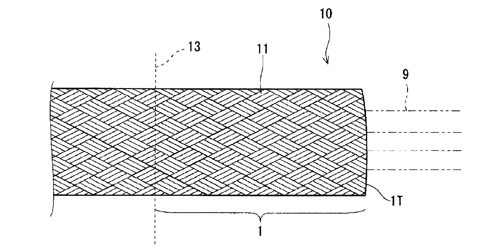
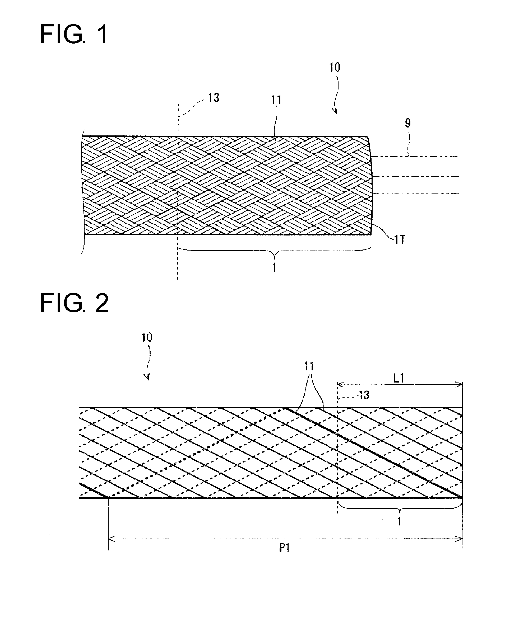
[0015]FIG. 1 is a side view showing a long braided conductor 10. The long braided conductor 10 is formed by braiding a plurality of strands 11 into a hollow tube by a braiding machine. More specifically, the long braided conductor 10 is configured by braiding a plurality of sets (picks), each pick composed of a plurality of strands 11, like a plain weave, i.e. by interlacing warp and weft threads so that the warp and weft threads are alternately located up and down. The strands 11 constituting the long braided conductor 10 are, for example, configured by conductors such as bare soft copper wires, oxygen-free soft copper wires or tin-plated soft copper wires.

[0016]A short braided conductor 1 is obtained by cutting the long braided conductor 10 at a desired...


PUM


Abstract

It is aimed to provide a technology for reducing the loosening of strands in a short-cut braided conductor. A short braided conductor 1 is obtained by cutting a long braided conductor 10 configured by braiding a plurality of strands 11 into a tubular shape to a desired cutting length (L1). The strands 11 are, for example, configured by conductors such as bare soft copper wires, oxygen-free soft copper wires or tin-plated soft copper wires. A spiral pitch (P1) of the strands 11 in this braided conductor 1 is preferably not less than twice and not more than five times of the cutting length (L1), more preferably not less than twice and not more than three times the cutting length (L1).

Description

BACKGROUND[0001]1. Field of the Invention[0002]The present invention relates to a braided conductor.[0003]2. Description of the Related Art[0004]Conventionally, a wiring harness with a braided conductor braided into a tubular shape is disclosed in Japanese Unexamined Patent Publication No. 2010-172162. Specifically, Japanese Unexamined Patent Publication No. 2010-172162 discloses a high-voltage wiring harness for electric vehicle in which wires are passed through a shield tube. The shield tube used here is formed by cutting a long braided conductor in the form of a mesh-like tube to a necessary length and applying a predetermined processing to end parts.[0005]Further, in recent years, it has been proposed to use braided conductors at various positions, taking advantage of flexibility and the like of the braided conductors. For example, Japanese Unexamined Patent Publication No. 2011-165428 discloses a braided conductor (flexible conductor) for electrically connecting a terminal of a...

Claims


Application Information

Patent Timeline
IPC IPC(8): H01B5/12
CPCH01B5/12H01R43/28H01B7/009
Inventor OMOTO, KATSUHIRO
Owner SUMITOMO WIRING SYST LTD
Learn More