Cleaning assembly and method for a shaft

a technology of cleaning assembly and shaft, which is applied in the direction of cleaning process and apparatus, accumulator installation, engine seals, etc., can solve the problems of premature spillage and leakage, reduced cylinder operating time, and increased wear resistance of tubular parts

Inactive Publication Date: 2016-06-09
INDS MAILHOT INC
View PDF2 Cites 1 Cited by
  • Summary
  • Abstract
  • Description
  • Claims
  • Application Information

AI Technical Summary

Benefits of technology

[0008]There is further provided a method for increasing resistance to wear of an tubular member of a telescopic cylinder comprising at least one tubular section with an open end and an opposite end closed by a cylinder head, the tubular section comprising an outer tubular member, an inner tubular member telescopically displaceable in the outer tubular member, and a shaver secured to an inner wall of the cylinder head, the method comprising providing at least one of: a cutting edge of the shaver having a round profile; an inner diameter of the shaver equal to an outer diameter of the inner tubular member; and a wear ring positioned between the shaver and a sealing ring of the cylinder head.

Problems solved by technology

Industrial telescopic cylinders may be exposed to a wide range of contaminants, especially when provided on refuse collection trucks or garbage compactors for example.
Such substances stick to surfaces of the cylinder heads and result in rapid damages of the sealing joints thereof, which may result in premature spills and leaks.
In garbage trucks, hydraulic cylinders may be submitted to large lateral forces, i.e. perpendicular to the axial thrust force of the cylinder, due to mechanical misalignment of the equipment or to the action of attached compactors for example which, cause wearing out of the surface roughness of the cylinders, which in turn reduces the operating time of the cylinders, as lubrication is reduced below an efficient lubrication, thereby reducing the life span of the cylinders.

Method used


Image

  • Cleaning assembly and method for a shaft
  • Cleaning assembly and method for a shaft
  • Cleaning assembly and method for a shaft

Examples


Embodiment Construction

[0025]For clarity purposes, the invention will be described in relation to a structure made of a series of series of tubular sections telescopically arranged in a tubular housing, each of the tubular sections having one end provided with a cylinder head, and comprising an inner tubular member telescopically displaceable in an outer tubular member respectively, such as a telescopic cylinder for example, intended for use in contaminated environments.

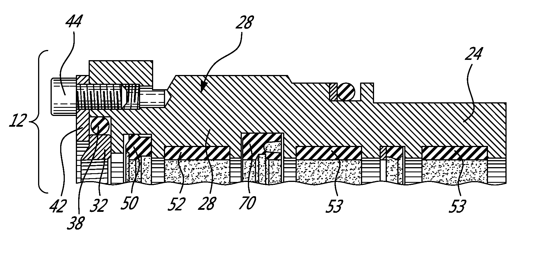
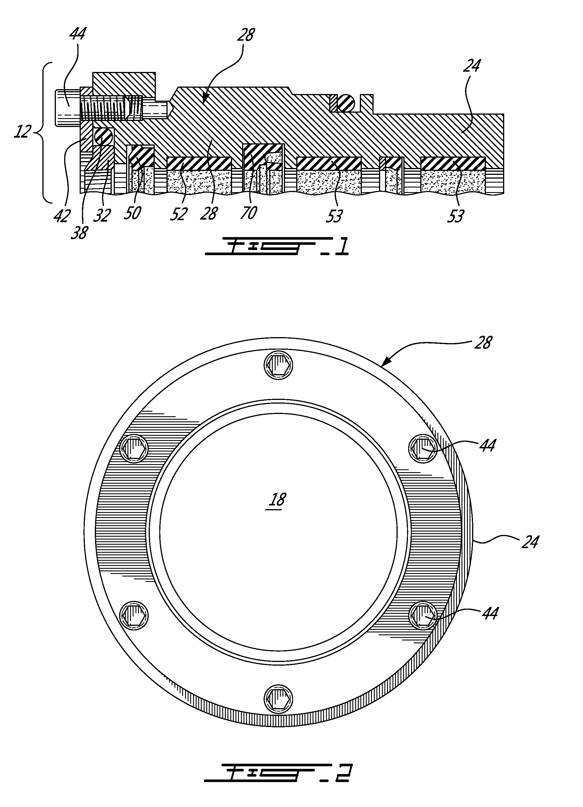
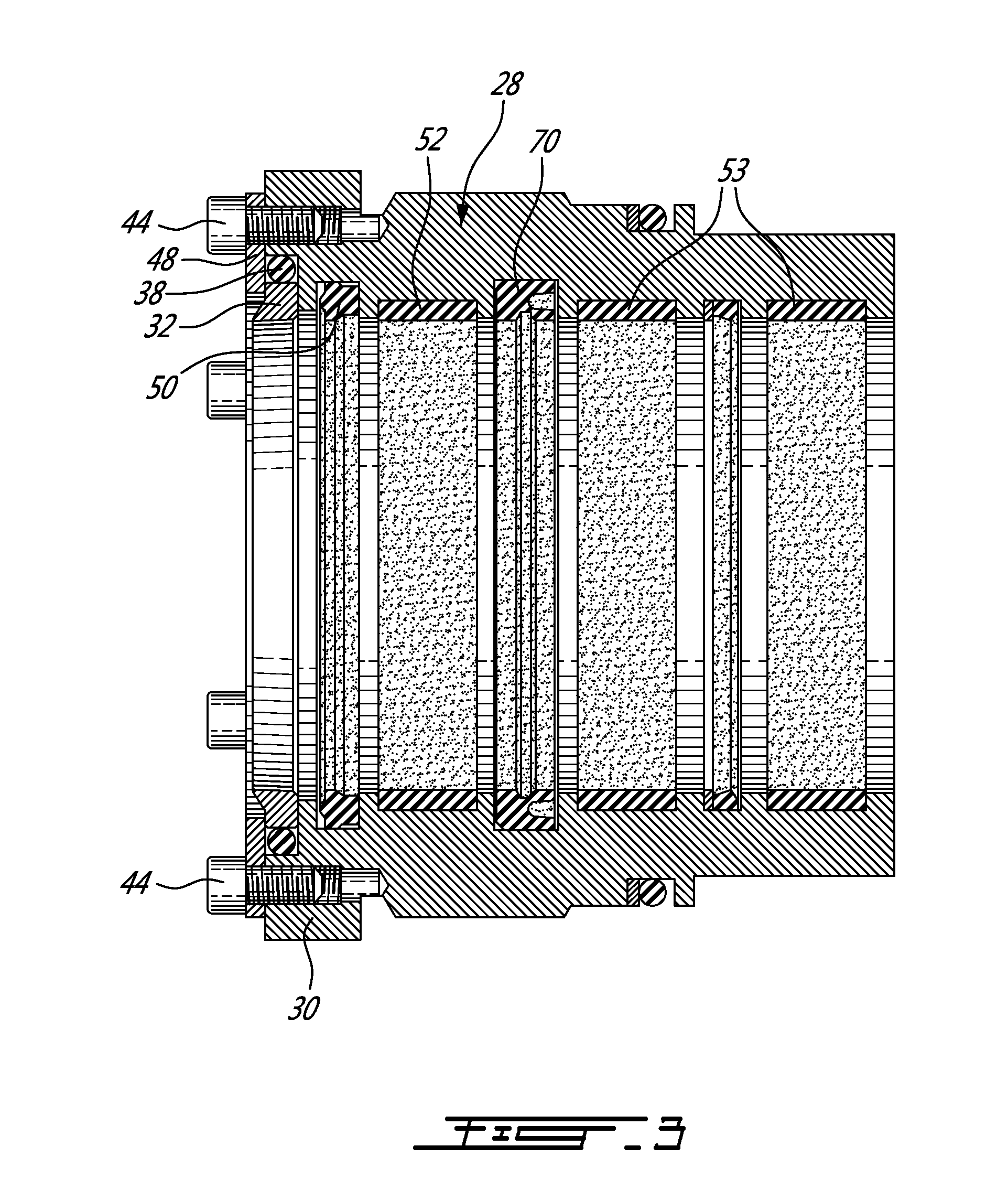
[0026]A telescopic cylinder may comprise a series of tubular sections 12, each tubular section comprising an inner tubular member 18 telescopically displaceable in an outer tubular member 24, with a wiper 50 mounted between the outer tubular member 24 and the inner tubular member 18. As illustrated for example in FIGS. 1-3, the tubular section 12 has one end provided with a cylinder head 28. The head 28 comprises a sealing ring 70 typically in a plastic material, urethane, or Teflon™ for example to prevent pressurized oil from leaking past...


PUM


Abstract

A method and a system for increasing resistance to wear of an tubular member of a telescopic cylinder comprising at least one tubular section with an open end and an opposite end closed by a cylinder head, the tubular section comprising an outer tubular member, an inner tubular member telescopically displaceable in the outer tubular member, and a shaver secured to an inner wall of the cylinder head, comprising using at least one of a cutting edge of the shaver having a round profile and/or an inner diameter of the shaver equal to an outer diameter of the inner tubular member; and/or a wear ring positioned between the shaver and a sealing ring of the cylinder head.

Description

CROSS REFERENCE TO RELATED APPLICATIONS[0001]This application claims benefit of U.S. provisional application Ser. No. 62 / 089,444, filed on Dec. 9, 2014. All documents above are incorporated herein in their entirety by reference.FIELD OF THE INVENTION[0002]The present invention relates to industrial telescoping cylinders. More specifically, the present invention is concerned with a cleaning assembly and method for a shaft.BACKGROUND OF THE INVENTION[0003]Industrial telescopic cylinders may be exposed to a wide range of contaminants, especially when provided on refuse collection trucks or garbage compactors for example. In refuse collection trucks, organic or mineral substances tend to adhere and accumulate on exposed surfaces of the vehicles, such as surfaces of sections of cylinder heads of the telescoping cylinders, where they cook under the action of heat. Such substances stick to surfaces of the cylinder heads and result in rapid damages of the sealing joints thereof, which may r...

Claims


Application Information

Patent Timeline
Patent Type & Authority Applications(United States)
IPC IPC(8): B08B9/023
CPCB08B9/023B08B1/008B08B1/02F16J15/56F15B15/1461F15B15/16F16J15/16F15B1/00
Inventor MAINVILLE, LUC
Owner INDS MAILHOT INC
Why Eureka
Try Eureka