Method for manufacturing a part coated with a protective coating

Active Publication Date: 2017-01-05
SN DETUDE & DE CONSTR DE MOTEURS DAVIATION S N E C M A
View PDF0 Cites 2 Cited by
  • Summary
  • Abstract
  • Description
  • Claims
  • Application Information

AI Technical Summary

Benefits of technology

[0046]The use of a counter-electrode of shape adapted to that of the part makes it possible, advantageously, for parts of relatively complex shape to avoid problems of how current lines are distributed. More generally, whatever the shape of the counter-electrode, it may be situated at a distance lying in the range 1 centimeter (cm) to 20 cm from the part. For example, the counter-electrode is situated at 2.5 cm from the

Problems solved by technology

Although such nickel-based superalloys are coated in a thermal barrier system, their utilization temperature can be limited to 1150° C. because of the proximity of their melting point.
Nevertheless, their oxidation behavior when hot can at present limit their use on a large scale.
The resulting oxide layer can

Method used


Image

  • Method for manufacturing a part coated with a protective coating
  • Method for manufacturing a part coated with a protective coating
  • Method for manufacturing a part coated with a protective coating

Examples


example

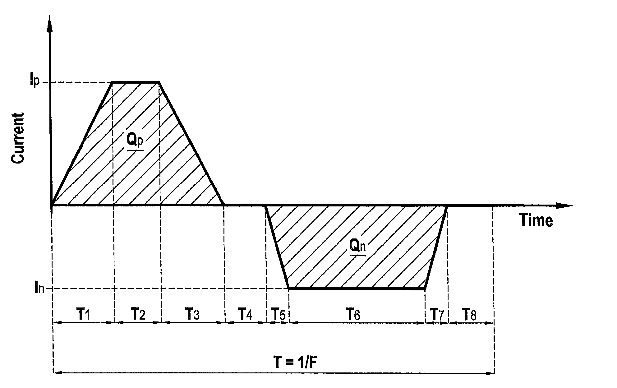
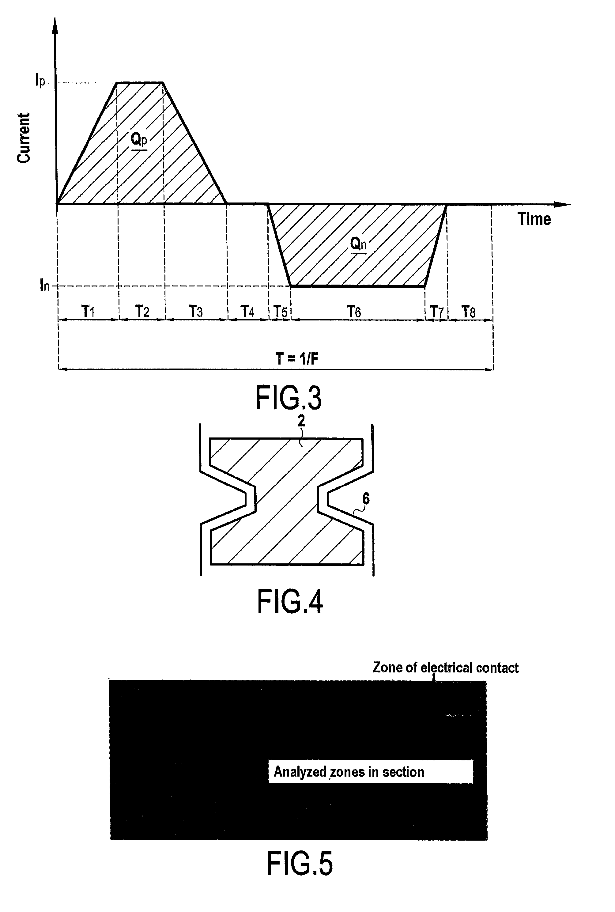
[0080]A substrate was treated by a method of the invention. Table 2 below gives the operating conditions (the times are expressed as a percentage of the total duration of the current cycle). The imposed cycle comprised the same succession of stages as the current cycle shown in FIG. 3.

TABLE 2Composition of thebasic substratebefore thebeginning of theComposition of themicro-arc oxidationelectrolyte beforetreatmentthe beginning of(% atomic): MASCElectricalthe micro-arcalloy (described inparametersoxidation treatmentU.S. Pat. No. 5,942,055)I (A) = 11NaOH = 0.4 g / LNb = 47%R = In / Ip = 55%Na2SiO2,5H2O = 15 g / LTi = 25%Frequency = 100 HzpH 12-13Hf = 8%Qp / Qn = 0.87solvent = waterCr = 2%T1 = 11%Al = 2%T2 = 20%Si = 16%T3 = 2%T4 = 1%T5 = 3%T6 = 61%T7 = 2%

[0081]After about 30 minutes of treatment, self-regulation conditions were reached, characterized by progressive extinction of the electric arc. The samples continued to be treated for five additional minutes under self-regulation conditions so...


PUM

PropertyMeasurementUnit
Temperatureaaaaaaaaaa
Fractionaaaaaaaaaa
Fractionaaaaaaaaaa

Abstract

A method of fabricating a part coated with a protective coating, the method including using micro-arc oxidation treatment to form a protective coating on the outside surface of a part, the part including a niobium matrix having metallic silicide inclusions present therein, the current passing through the part being controlled during the micro-arc oxidation treatment in order to subject the part to a succession of current cycles, the ratio of (quantity of positive charge applied to the part)/(quantity of negative charge applied to the part) lying in the range 0.80 to 1.6 for each current cycle.

Description

BACKGROUND OF THE INVENTION[0001]The invention relates to parts coated with a protective coating, and to methods of fabricating such parts.[0002]At present, for the hottest parts in turbine engines, only nickel-based superalloys are used on an industrial scale. Although such nickel-based superalloys are coated in a thermal barrier system, their utilization temperature can be limited to 1150° C. because of the proximity of their melting point.[0003]Recent research work has focused on using novel materials based on refractory metals capable of being used at temperatures higher than the utilization temperatures of nickel-based superalloys. These families of materials are commonly referred to as: refractory metal-intermetallic composites (RMICs).[0004]Among the solutions that have been found, niobium-based alloys appear to be particularly promising for replacing, or for being used together with, existing nickel-based superalloys. These various alloys have the advantage of presenting mel...

Claims


Application Information

Patent Timeline
IPC IPC(8): C25D11/26C25D11/02
CPCC25D11/024C25D11/026C25D11/26C25D21/12
Inventor KNITTEL, STEPHANE
Owner SN DETUDE & DE CONSTR DE MOTEURS DAVIATION S N E C M A
Why Eureka
Try Eureka