System for modular building construction

Inactive Publication Date: 2016-06-09
GLOBAL BUILDING MODULES
View PDF10 Cites 67 Cited by
  • Summary
  • Abstract
  • Description
  • Claims
  • Application Information

AI Technical Summary

Benefits of technology

[0012]In accordance with the preferred embodiment of the invention, an architectural building system is provided which consists of interconnectable prefabricated modular volumetric units of building construction, each comprising a steel frame shaped as a rectangular parallelopiped that utilizes the ISO cargo container as the basis for its exterior dimensions, the frame comprised of framing members and a steel corner fitting or brack

Problems solved by technology

These changes, among many others, led to a vastly more complex society that demanded larger and more elaborate structures to house new living, work, social, and cultural functions.
Widely varying dimensional tolerances between factory and field methods lead to excessive allowances for fitting, which in turn encourages sloppy joinery.
Three-dimensional coordination of components, such as ductwork and piping, with structural and spatial restrictions, is done in the field under intense schedule pressure, and there is only one opportunity to get it right; frequently a ceiling is lowered or boxed out to accommodate errors, and even less desirable accommodations that sacrifice the quality of design and function are not uncommon.
This typical method of building construction, although traditional, does not take full advantage of the principles of industrialization, including the mass production of, interchangeable parts and assembly in a controlled factory setting.
Historically, the primary reason for this failure has been that most buildings, especially multi-story buildings, are too large to be cost-effectively moved from a factory to the erection site, i.e, the logistics of transportation do not suggest an obvious way of making entire buildings in factories.
Another reason is that members of the craft-based construction industry (including the design professions) have not realized anywhere near the full potential of industrial methods and advances in information technology.
Finally, the perception that the quality and versatility of “pre-fabricated” buildings is lower than that of manufactured buildings has created a stigma associated with the term “modular” construction.
However, generally speaking the high cost of transporting oversize loads has limited the distribution range of conventional modular factories to a five hundred mile radius.
This limit of distribution range has stunted the growth of the conventional modular manufacturing industry and h

Method used


Image

  • System for modular building construction
  • System for modular building construction
  • System for modular building construction

Examples


Embodiment Construction

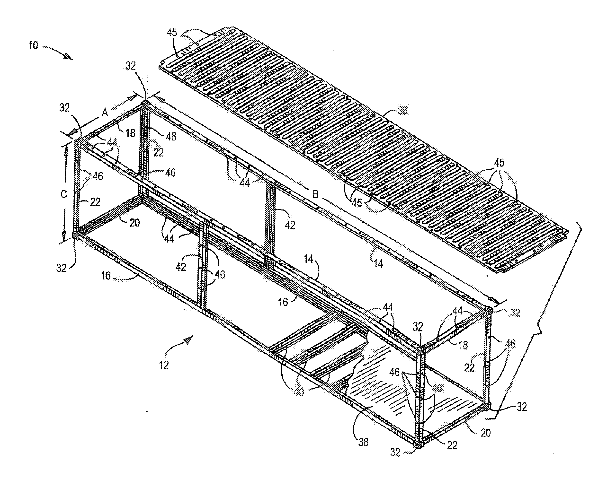
[0175]The preferred embodiments of the present invention, as well as other embodiments thereof, will now he further described with reference to the accompanying drawings, wherein like reference numerals designate like or corresponding parts throughout the several views. Although the invention will be illustratively described hereinafter and is shown in the drawings mostly with reference to residential construction, it should be understood that the invention is not limited to residential environments, but could be utilized in the construction of other single- and multi-story structures, including, but not limited to, office, retail, industrial, place of assembly, educational and laboratory structures.

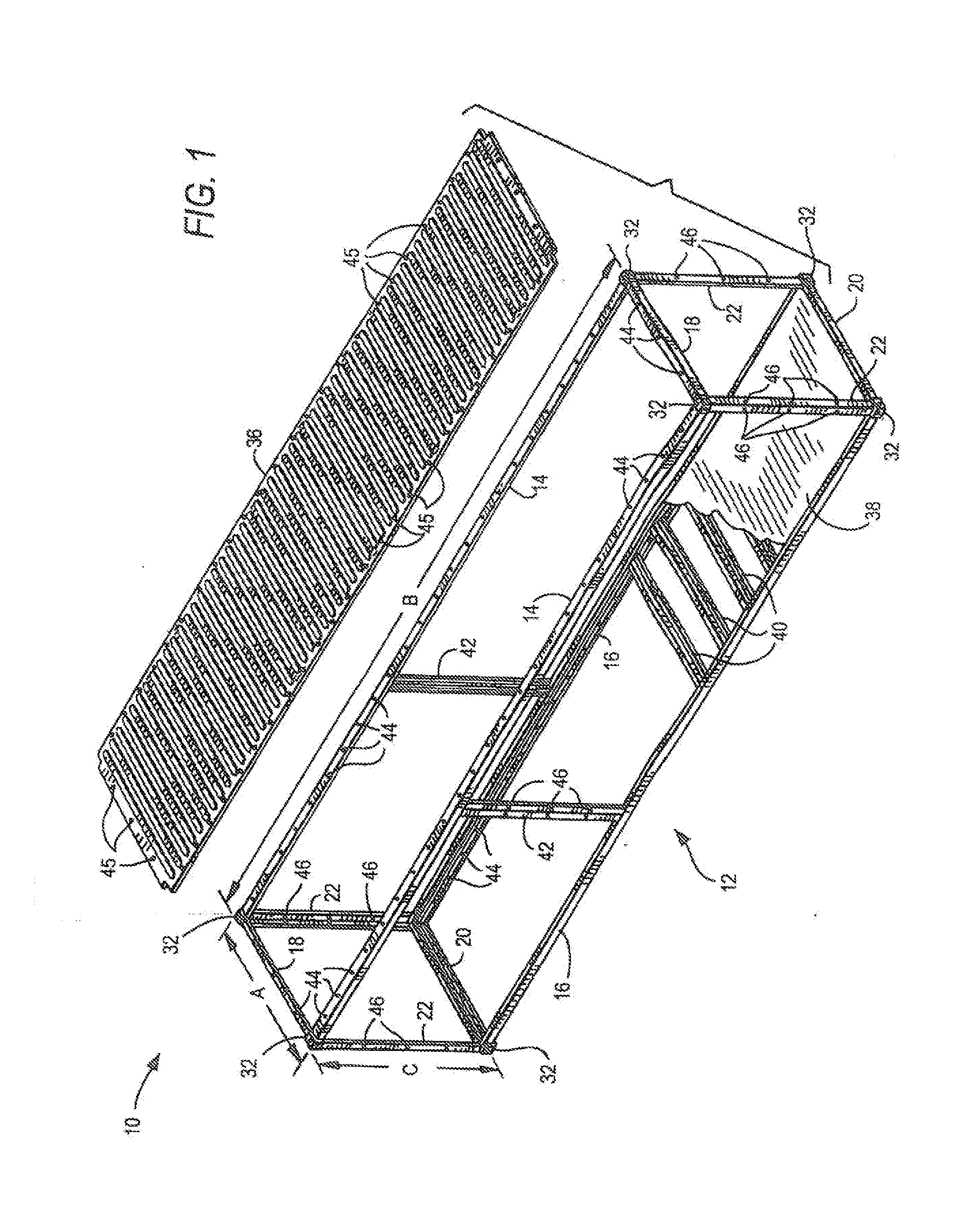
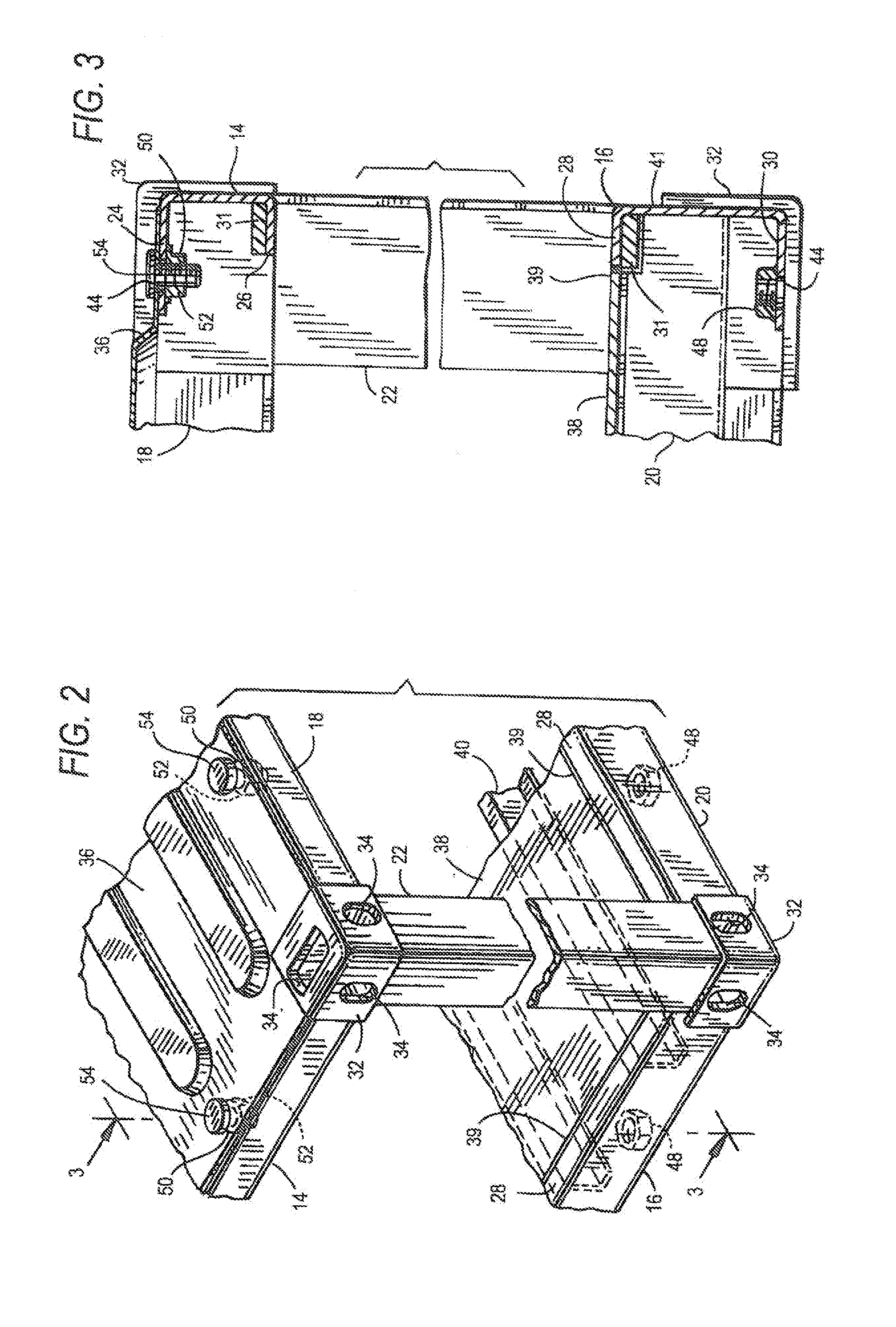
[0176]Referring now to the drawings, and initially to FIGS. 1-5, a modular, volumetric unit of construction (hereinafter “VUC”), manufactured in accordance with the preferred embodiment of the present invention, is generally designated 10. VUC 10 comprises a skeletal frame 12, the overal...


PUM


Abstract

Construction systems for erecting budding structures comprise a plurality of prefabricated interconnectable modular budding units, each unit comprising framing members and a plurality of nodes, each node situated for selective interconnection with other units, the nodes and the exterior dimensions of the frame conforming to ISO shipping standards such that each unit is transportable using the ISO intermodal transportation system, and such that when the units are interconnected, a building structure is formed. The modular units are assembled at a remote location, and are there constructed to a semi-finished state, following which the semi-finished modular units are transported from the remote location to the job site, where they are secured to form the structure being erected, and the semi-finished modular units are thereafter constructed to a finished state.

Description

REFERENCE TO RELATED APPLICATIONS[0001]This application is a continuation-in-part of prior co-pending application Ser. No. 14 / 811,903, filed Jul. 29, 2015, which was a continuation of application Ser. No 14 / 339,590, filed Jul. 24, 2014, now U.S. Pat. No. 9,115,504, which was a continuation of prior co-pending application Ser. No 13 / 770,278, filed Feb. 19, 2013, now U.S. Pat. No 8,826,600, which was a continuation of prior co-pending application Ser. No.13 / 171,534, filed Jun. 29, 2011, now U.S. Pat. No. 8,397,441, which was a continuation of prior co pending application Ser. No 12 / 900041, filed Oct. 7, 2010, now U.S. Pat. No 8,001,730, which was a continuation of prior co-pending application Ser. No 11 / 893,639, filed Aug. 17, 2007, now U.S. Pat. No 7,827,738, which claimed the benefit under 35 U.S.C. §119(e) of the following prior co-pending U.S. Provisional Patent Applications: Ser. No. 60 / 840,419, filed Aug. 26, 2006, Ser. No 60 / 843,247, filed Sep. 8, 2006; Ser. No 60 / 861,407, file...

Claims


Application Information

Patent Timeline
IPC IPC(8): E04H1/00E04B1/343E04B1/348E04H1/04
CPCE04H1/005E04H1/04E04B1/343E04B1/348E04B1/34331E04B1/34336E04B1/34384E04B1/34321E04B1/003E04B1/34807E04B1/3483F24D3/145E04B2001/34892E04B1/0015E04B2001/3583E04F10/08E04F10/10E04F10/005Y02B30/00
Inventor WALLANCE, DAVID
Owner GLOBAL BUILDING MODULES
Why Eureka
Try Eureka