Abrasive coated substrate and method for manufacturing thereof

a technology of abrasive coating and coating substrate, which is applied in the direction of aluminum oxide/hydroxide, liquid fuel engine components, non-positive displacement fluid engine, etc., can solve the problems of reducing efficiency considerably, unable to ensure a sufficient protection, and the protective effect of an abrasive coating can only be provided for a very short time, so as to achieve rapid and inexpensive production

Active Publication Date: 2016-06-09
ANSALDO ENERGIA SWITZERLAND AG
View PDF19 Cites 17 Cited by
  • Summary
  • Abstract
  • Description
  • Claims
  • Application Information

AI Technical Summary

Benefits of technology

[0022]According to yet another advantageous aspect of the invention, before the formation of the coating, the abrasive particles are coated. In a first step, the first particle coating layer is formed on the abrasive particles. Preferably a method is used, such that the first particle coating layer is chemically bonded to the substrate material. A suitable method is salt bath deposition. In the following optional step the secondary layers can be depos

Problems solved by technology

This measure reduces the efficiency considerably.
However, at operating temperatures above 800° C. to 850° C. cBN is oxidizing with the result that a protective effect of an abrasive coating can only be provided for a very s

Method used


Image

  • Abrasive coated substrate and method for manufacturing thereof
  • Abrasive coated substrate and method for manufacturing thereof
  • Abrasive coated substrate and method for manufacturing thereof

Examples


Embodiment Construction

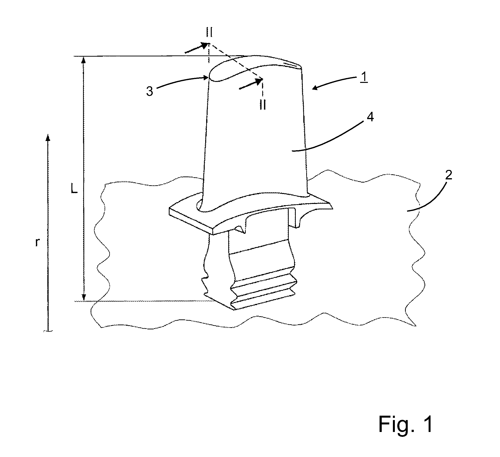
[0030]FIG. 1 shows a turbine blade 1 for a rotor 2 (shown schematically) of a gas turbine. The turbine blade 1 can have a directionally solidified or a single-crystalline basic body 4, which extends in the radial direction r (in relation to the rotor) with a length L and ends at a radially outer blade tip 3.

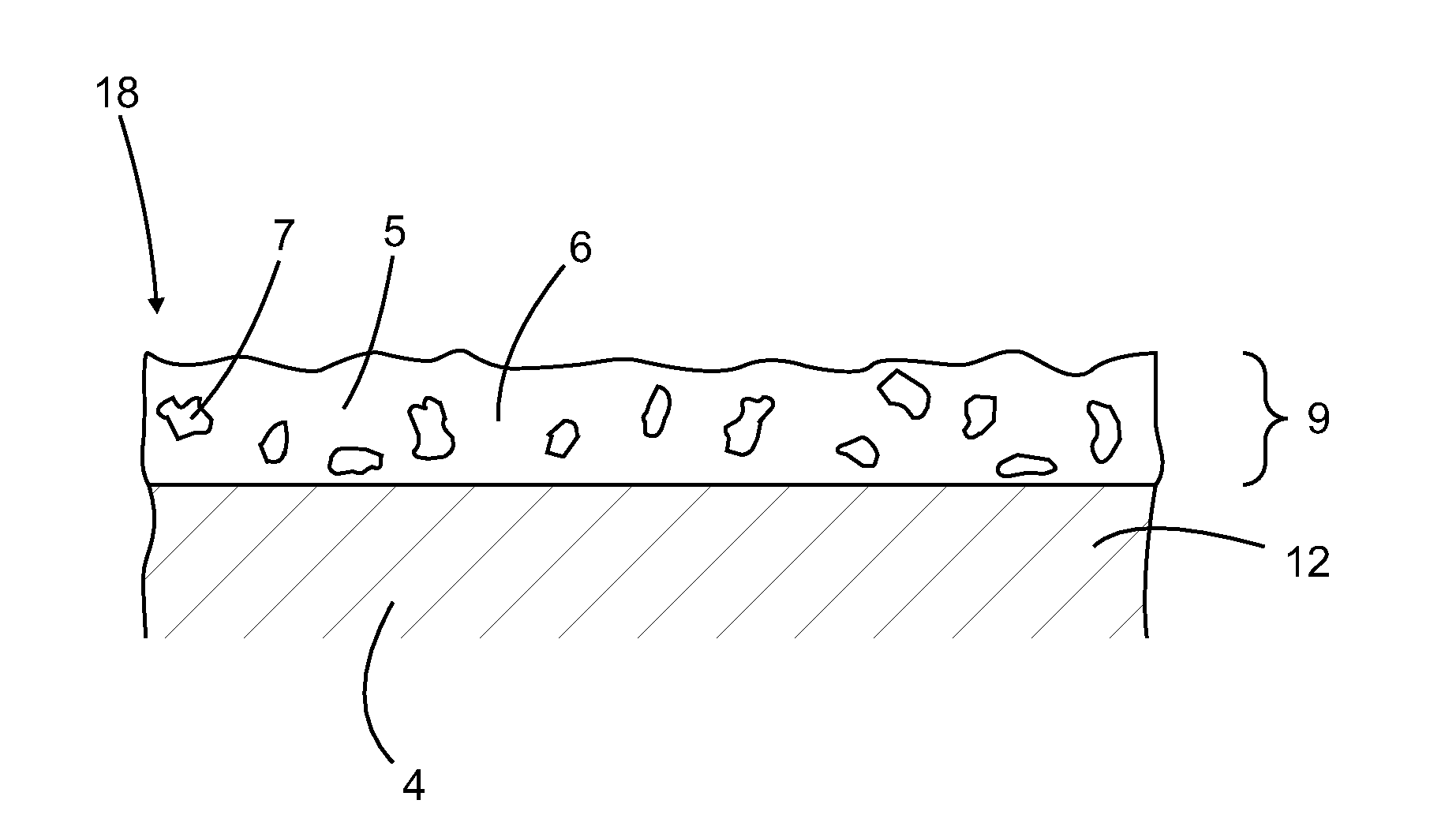
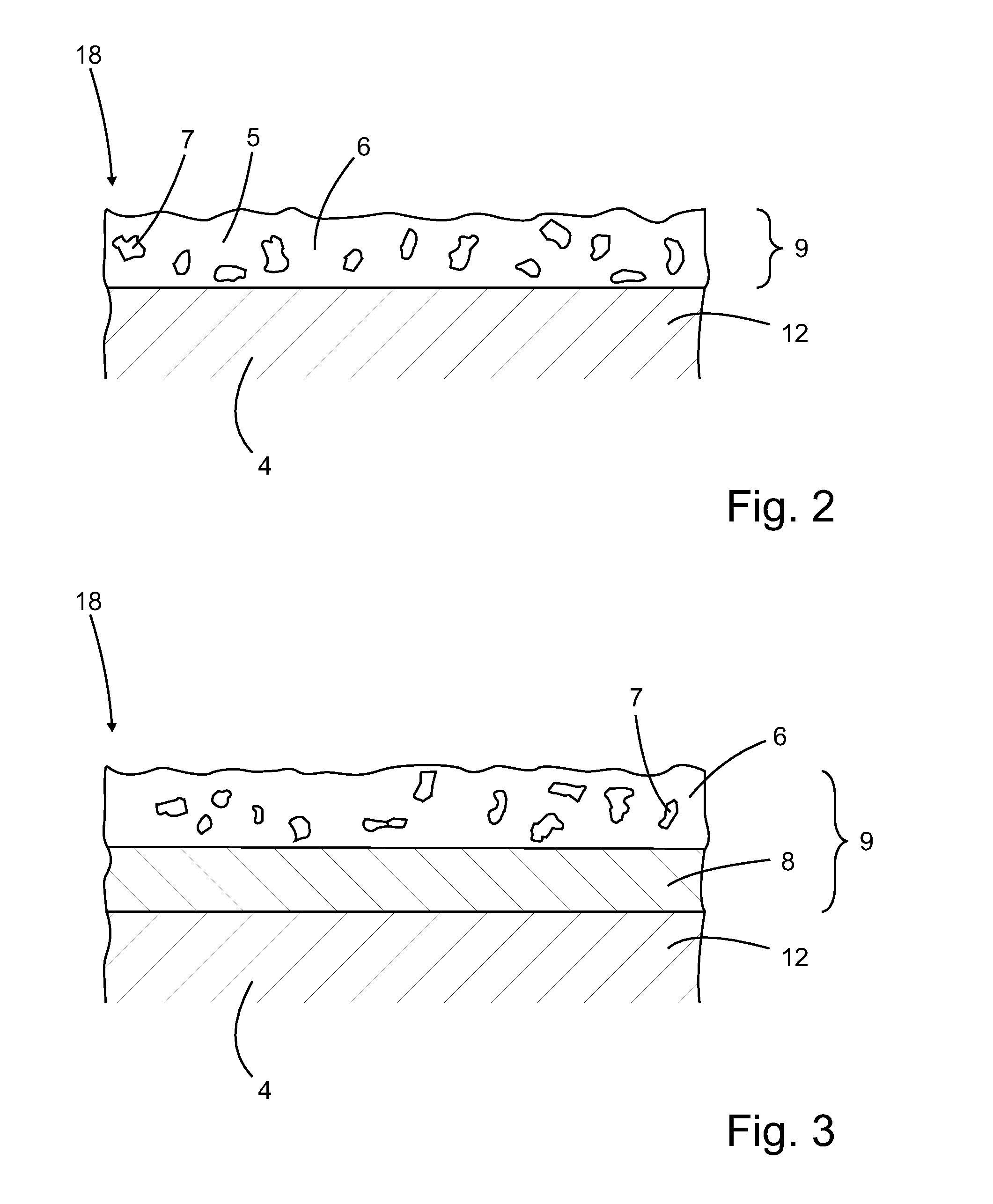
[0031]According to FIG. 2, the substrate material 12 represented by the basic body 4, is coated with an abrasive coating layer 5. Thus a coated substrate 18 is produced. The coated substrate 18 according to the present application can be a new or a reconditioned turbine blade.

[0032]The abrasive coating layer 5 consists of a matrix material 6, which consists of the compound MCrAlY, and of abrasive particles 7 consisting of single-crystalline α-Al2O3, which are embedded in the matrix material 6.

[0033]As schematically shown in FIG. 4, the abrasive particles 7 are coated with a first coating layer 19 consisting e.g. of titanium formed by salt bath deposition disposed on the abrasive ...


PUM

PropertyMeasurementUnit
Temperatureaaaaaaaaaa
Electrical resistanceaaaaaaaaaa
Abrasiveaaaaaaaaaa

Abstract

A coated substrate is described including a substrate material, which is coated at least in part with an oxidation-resistant coating, wherein the coating consists of a wear-resistant abrasive coating layer, which contains or consists of coated abrasive particles embedded in an oxidation-resistant matrix material, wherein at least some of the abrasive particles consist of α-Al2O3 and the abrasive particles are coated with a first particle coating layer disposed on the abrasive particles and an optional second particle coating layer disposed on the first particle coating layer, wherein the matrix material contains or consists of the compound MCrAlY, wherein M is at least one element selected from the group consisting of Ni, Co and Fe. A method for manufacturing such a coated substrate is also disclosed.

Description

TECHNICAL FIELD[0001]The present invention relates to a coated substrate comprising a substrate material, which is coated at least in part with an oxidation-resistant coating, wherein the coating consists of or comprises a wear-resistant abrasive coating layer, which consists of coated abrasive particles embedded in an oxidation-resistant matrix material. The invention also relates to a manufacturing method thereof. Such substrate materials can, for example, consist of a single-crystalline superalloy, wherein the substrate material is a radially extending turbine blade for a turbine rotor, and wherein the coating is applied at the radially outer blade tip surface.BACKGROUND OF INVENTION[0002]During transient processes, such as start, restart, shut-down or load changes in gas turbines and compressors, the distance between the rotor blades and the static components, such as heat-shields, are varying. Commonly, a rubbing of the rotor blades is circumvented by a sufficiently high distan...

Claims


Application Information

Patent Timeline
IPC IPC(8): F01D5/28C23C26/02C01F7/02B23K26/144B23K26/06B23K26/03B32B15/01B23K26/34C09D7/62
CPCF01D5/288F05D2300/135C23C26/02B23K26/34B23K26/144B23K26/0626B23K26/034C01F7/02F05D2220/32F05D2230/90F05D2240/307F05D2300/174F05D2300/177F05D2300/132F05D2300/131F05D2300/134B32B15/01C22C19/057C23C4/12B23K26/0006C09D1/00C08K9/02C23C28/022C08K2003/2227F01D11/122C09K3/1436C09K15/04C23C24/103C23C28/027C09D7/62B23K2101/001B23K2103/08B23K2103/26
Inventor BALBACH, WERNER MARTINEBELING, WILHELMHOEBEL, MATTHIAS
Owner ANSALDO ENERGIA SWITZERLAND AG
Why Eureka
Try Eureka