Method of installing elastomer ring in semiconductor processing equipment and guiding sheet and jig used in installing elastomer ring

a technology of elastomer ring and installation method, which is applied in the direction of manufacturing tools, metal working apparatus, electric discharge tubes, etc., can solve the problems of affecting the performance affecting so as to achieve accurate prediction of the life of the elastomer ring, the effect of effectively preventing fluid leakage from

Active Publication Date: 2016-06-09
MFC SEALING TECH
View PDF1 Cites 1 Cited by
  • Summary
  • Abstract
  • Description
  • Claims
  • Application Information

AI Technical Summary

Benefits of technology

[0014]The advantage of the present invention is utilizing the guiding sheet and the partial filling jig to move the elastomer ring into the groove step by step. The elastomer ring is disposed in the groove evenly through the manual operation to ensure that the semiconductor processing equipment works well. The lifetime of the elastomer ring can be accurately predicted and the fluid leak from the slits between the susceptor body and the connecting portion is effectively prevented.
[0015]Particularly, multiple points of the elastomer ring are pressed in a particular sequence by the partial filling jig along an outer surface of the elastomer ring. The method further comprises: defining the outer surface of the elastomer ring equally into multiple arcs. Then the partial filling jig presses each one of the multiple arcs gradually. Each one of the multiple arcs includes two endpoints, one midpoint, and two relay points respectively. The two endpoints are the first endpoint and the second endpoint, and the two relay points are the first relay point and the second relay point. The midpoint is in the middle between the first endpoint and the second endpoint. The first relay point is in the middle between the second endpoint and the midpoint, and the second relay point is in the middle between the first endpoint and the midpoint. The particular sequence is that the partial filling jig presses the first endpoint before pressing the second endpoint, and then the partial filling jig presses the midpoint. Finally, the partial filling jig presses the second relay point after pressing the first relay point. The step of filling partially is finished when the multiple arcs are all filled through the particular sequence. The advantage of the present invention is that the outer surface of the elastomer ring may be pressed in the particular sequence by the partial filling jig. Then the elastomer ring moves into the groove smoothly and evenly. In addition, the elastomer ring does not rotate in the groove. The elastomer ring may not protrude from the groove to impede the working of the semiconductor processing equipment.
[0016]More particularly, multiple points on the elastomer ring and multiple segments of the elastomer ring are pressed and rolled in a particular sequence by the full filling jig along an outer surface of the elastomer ring. The method further comprises: defining the outer surface of the elastomer ring equally into multiple arcs first. The full filling jig presses each arc of the multiple arcs gradually. Each arc of the multiple arcs includes two terminal points, one intermediate point, and two rolling segments respectively. The two terminal points are the first terminal point and the second terminal point, and the two rolling segments are the first rolling segment and the second rolling segment. The intermediate point is in the middle between the first terminal point and the second terminal point. The first rolling segment is between the first terminal point and the intermediate point, and the second rolling segment is between the second terminal point and the intermediate point. The particular sequence is that the full filling jig presses the first terminal point before pressing the intermediate point, and then the full filling jig rolls the first rolling segment from the intermediate point to the first terminal point. Finally, the full filling jig rolls the second rolling segment from the second terminal point to the intermediate point after pressing the second terminal point. The step of filling fully is finished when the multiple arcs are all pressed and rolled through the particular sequence. The advantage of the present invention is that the outer surface of the elastomer ring may be pressed in the particular sequence by the full filling jig. Then the elastomer ring further moves into the groove after pressing by the full filling jig regularly. The groove is filled by the elastomer ring completely. The elastomer ring has a specific lifetime after the elastomer ring is installed into the groove with accuracy and conformity. Users may timely replace the elastomer ring before the leaking and the erosion occur.
[0017]Perfectly, the cross-section of the elastomer ring is a rectangle. The elastomer ring comprises a radial width and a height. The ratio of the radial width to the height is larger than 0.5. A side of the elastomer ring toward the groove comprises two edges. The two edges are chamfered edges respectively. The advantage of the present invention is that the elastomer ring with the specific ratio of the radial width and the height may move into the groove easily through the designs of the two chamfered edges.
[0018]The present invention further provides a guiding sheet for installing the elastomer ring in a semiconductor processing equipment. The guiding sheet comprises: a body portion and a bending portion. The body portion connects to the bending portion. An angle is formed between the body portion and the bending portion. The notch is recessed on a side of the bending portion, and the side of the bending portion is opposite to the body portion. The notch is corresponding to the elastomer ring in shape. The advantage of the present invention is that the elastomer ring may be covered and accommodated by the notch of the guiding sheet. The elastomer ring may be moved to align to the groove with the guiding sheet. The guiding sheet guides the elastomer ring to align to the groove before pressing by the partial filling jig. Then the elastomer ring may be pressed into the groove smoothly and evenly.
[0019]The present invention further provides a partial filling jig for installing the elastomer ring in a semiconductor processing equipment. The partial filling jig comprises two semicircular structures and two packing assemblies. The inner sides of the two semicircular structures are opposite each other, and the inner sides of the two semicircular structures are corresponding to the elastomer ring in shape. Each one of the two semicircular structures comprises two ends, and two protrusions are formed on the two ends of each one of the two semicircular structures respectively. The two protrusions protrude toward the outer side of each one of the two semicircular structures respectively. The two packing assemblies are mounted on the two protrusions of each semicircular structure respectively. The advantage of the present invention is that the two semicircular structures may be connected by the packing assembly on the two ends of each semicircular structure. A circular space is formed by connecting the two semicircular structures. The area of the circular space may be regulated by the packing assembly, and the elastomer ring may be restricted in the circular space. If the area of the circular space becomes smaller through the packing assembly, the elastomer ring will be pressed by the two semicircular structures more strongly. Then the elastomer ring may be moved into the groove evenly.

Problems solved by technology

The fluid 121 may also flow into the passage through the slits and damage the conventional semiconductor processing equipment.
In addition, the fluid 121 may induce pollution of the environment.
It is not easy to install the elastomer ring 180 into the groove 160.
Many problems still exist in installing the elastomer ring 180 in a semiconductor processing equipment.

Method used


Image

  • Method of installing elastomer ring in semiconductor processing equipment and guiding sheet and jig used in installing elastomer ring
  • Method of installing elastomer ring in semiconductor processing equipment and guiding sheet and jig used in installing elastomer ring
  • Method of installing elastomer ring in semiconductor processing equipment and guiding sheet and jig used in installing elastomer ring

Examples


Embodiment Construction

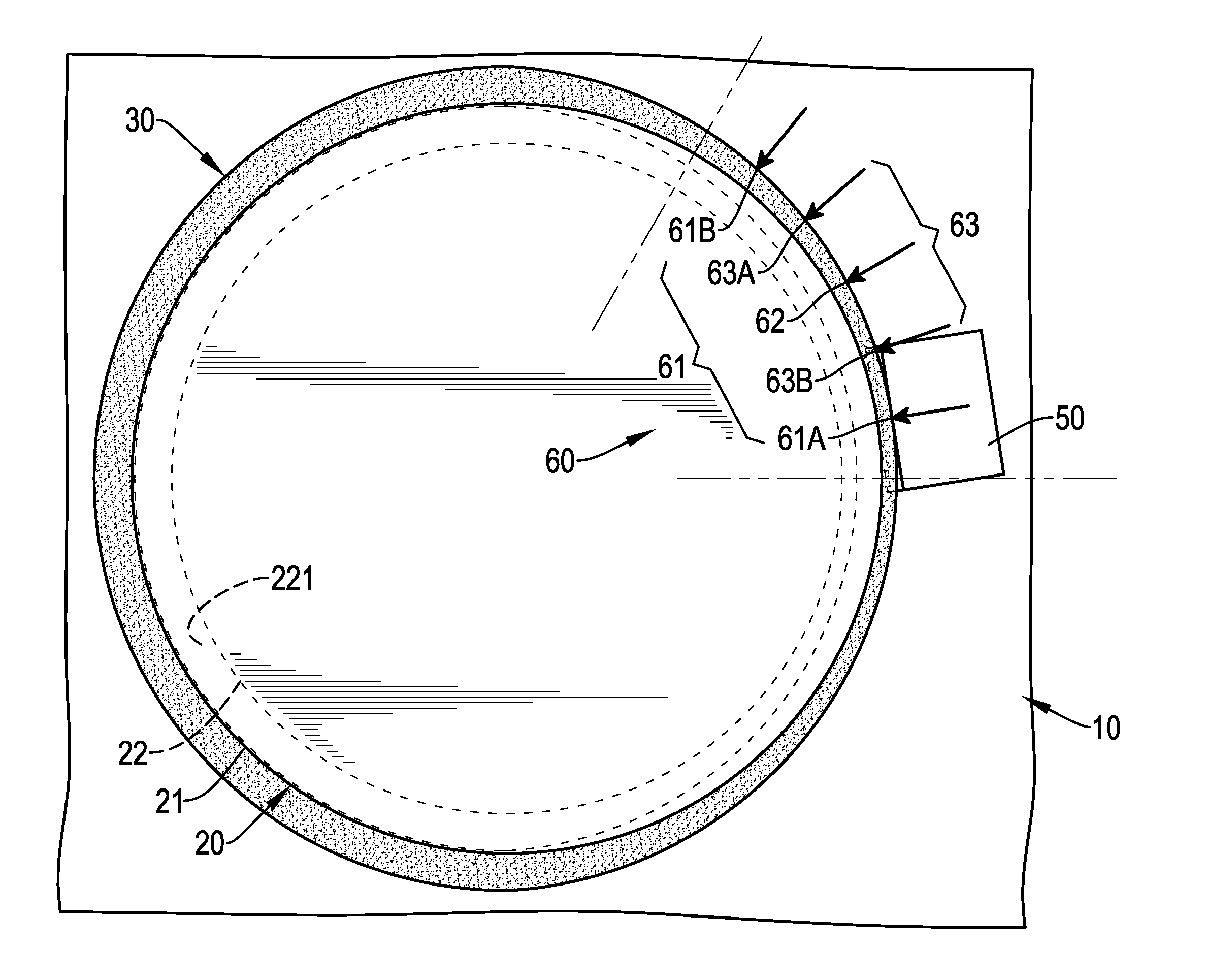
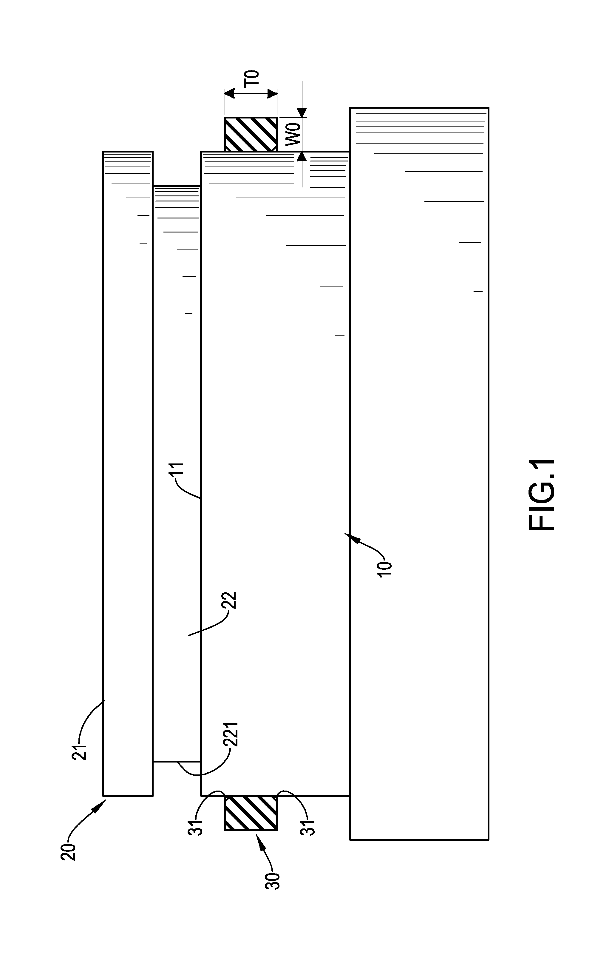
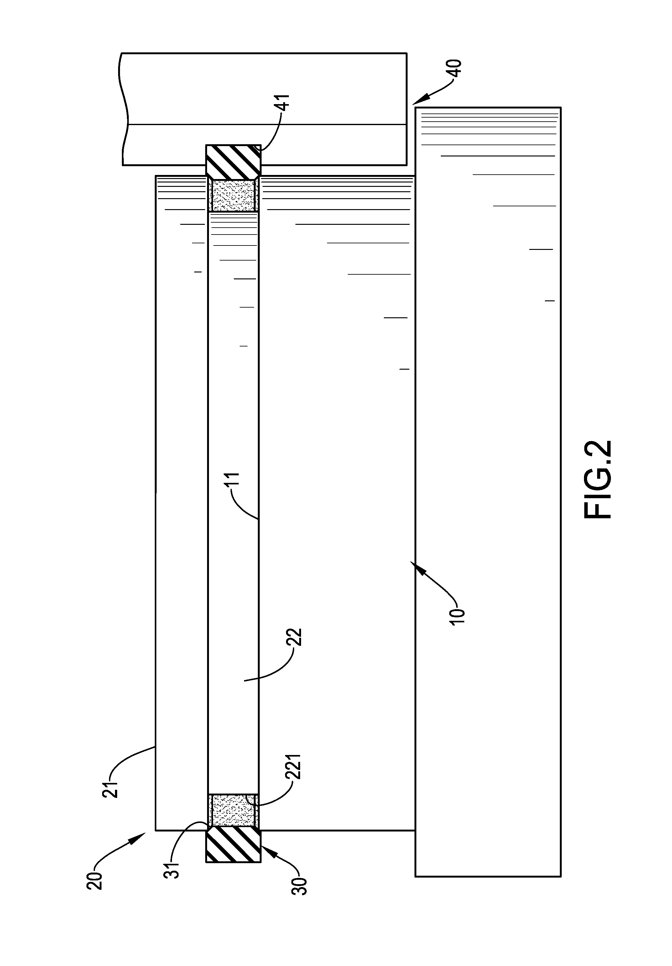
[0054]With reference to FIG. 1, the semiconductor processing equipment comprises a susceptor body 10 and a supporting element 20. The susceptor body 10 has a top surface 11, and the supporting element 20 further has a top portion 21 and a connecting portion 22. The supporting element 20 is disposed on the top surface 11 of the susceptor body 10, and the connecting portion 22 of the supporting element 20 connects with the susceptor body 10 and the supporting element 20. A groove 221 is formed on the outer surface of the connecting portion 22, and the groove 221 is among the top surface 11, the top portion 21, and the connecting portion 22.

[0055]The first step of a method for installing an elastomer ring 30 in the semiconductor processing equipment in accordance with the present invention is preliminary disposing the elastomer ring. The elastomer ring 30 is mounted to the side surface of the susceptor body 10 and is close to the top surface 11. The elastomer ring 30 is stretched throu...


PUM

PropertyMeasurementUnit
radial widthaaaaaaaaaa
heightaaaaaaaaaa
angleaaaaaaaaaa

Abstract

Provided are a method, a guiding sheet, a partial filling jig, and a full filling jig for installing an elastomer ring in the semiconductor processing equipment. The guiding sheet, the partial filling jig, and the full filling jig dispose the elastomer ring in the groove of the semiconductor processing equipment smoothly and evenly. Furthermore, the surface of the elastomer ring may be divided to multiple arcs portions. Each one of the arc portions may be pressed by the partial filling jig or the full filling jig in a particular sequence. When the groove is filled by the elastomer ring accurately and completely, the elastomer ring may block the fluid and the etching gas effectively. The elastomer ring may help the semiconductor processing equipment to work continuously and maintain qualities of the etching wafers.

Description

BACKGROUND OF THE INVENTION[0001]1. Field of the Invention[0002]The present invention relates to a method of installing an elastomer ring in a semiconductor processing equipment, and more particularly to a method of installing the elastomer ring into a groove of the semiconductor processing equipment with accuracy and conformity. In addition, the present invention also provides a guiding sheet and a jig to install the elastomer ring in the semiconductor processing equipment.[0003]2. Description of the Related Art[0004]Conventional semiconductor processing equipment is shown in FIGS. 18 and 19. The conventional semiconductor processing equipment comprises a chamber 100, and a susceptor 110, a fluid supplying unit 120, a supporting element 130, and an extending cover 140 are mounted in the chamber 100. The wafer 150 is disposed on the supporting element 130, and the wafer 150 is etched by etching gas 170. The supporting element 130 is disposed on the susceptor 110. The fluid supplying...

Claims


Application Information

Patent Timeline
Patent Type & Authority Applications(United States)
IPC IPC(8): H01J37/32B25B27/00
CPCH01J37/32807H01J2237/334B25B27/0092B25B27/02B25B27/0028H01L21/67126
Inventor CHANG, YO-YUHUANG, CHUN-YAO
Owner MFC SEALING TECH
Why Eureka
Try Eureka