Supercharge Your Innovation With Domain-Expert AI Agents!

Terminal module

Active Publication Date: 2016-06-09
DAIICHI SEIKO CO LTD
View PDF11 Cites 2 Cited by
  • Summary
  • Abstract
  • Description
  • Claims
  • Application Information

AI Technical Summary

Benefits of technology

The present invention provides a terminal module that prevents accuracy issues in the position of the electrically conductive terminals relative to the heat radiation board and prevents bonding defects between the terminals and the electric elements. This is achieved by integrating the terminal directly onto the first board or via a frame, which prevents frame deformation and shrinkage. The module also allows for different numbers of terminals to be included without requiring a mold change, ensuring usability flexibility.

Problems solved by technology

The part unit 900 illustrated in FIG. 68 is accompanied with a problem in that if the frame 904 is designed to be large in size, the frame 904 would be likely to be curved and / or deformed with the result of deterioration in accuracy of flatness thereof, causing a defect in bonding between the electrically conductive terminals 903 mounted on the frame 904 and the electric elements 901 mounted on the heat radiation board 902.
Furthermore, shrinkage of a synthetic resin of which the frame 904 is made causes deterioration in accuracy in positioning of the electrically conductive terminals 903.
However, since the electrically conductive terminals 903 are individually mounted on the frame 904, it is quite difficult or almost impossible to amend a mold, resulting in that the mold might not be amended in a desired manner.
However, such a resin brings cost-up in the fabrication of the frame 904, and accordingly, it is not actually allowed to use such a resin for fabrication of the frame 904.
The process of fabricating a power module disclosed in the above-identified Japanese Patent Application is considered to be accompanied with the problems as mentioned above.

Method used


Image

  • Terminal module
  • Terminal module
  • Terminal module

Examples


first embodiment

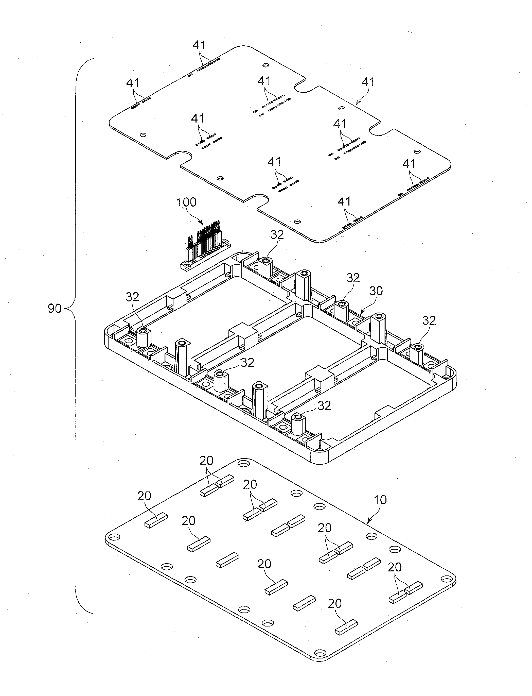
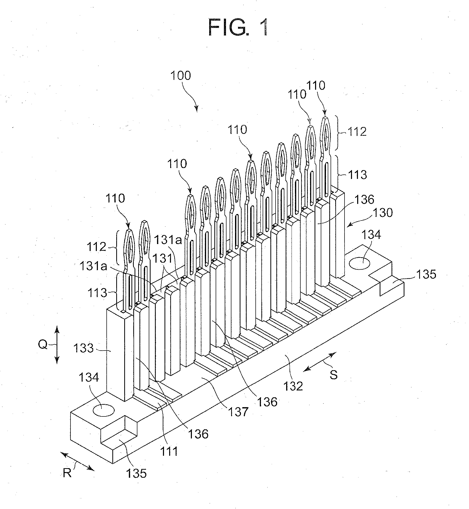
[0093]A terminal module 100 according to the first embodiment of the present invention is explained hereinbelow with reference to FIGS. 1 to 15. In the specification, a direction indicated with an arrow Q illustrated in FIG. 1 indicates an up-down direction, a direction indicated with an arrow R illustrated in FIG. 1 indicates a front-rear direction, and a direction indicated with an arrow S illustrated in FIG. 1 indicates a left-right direction.

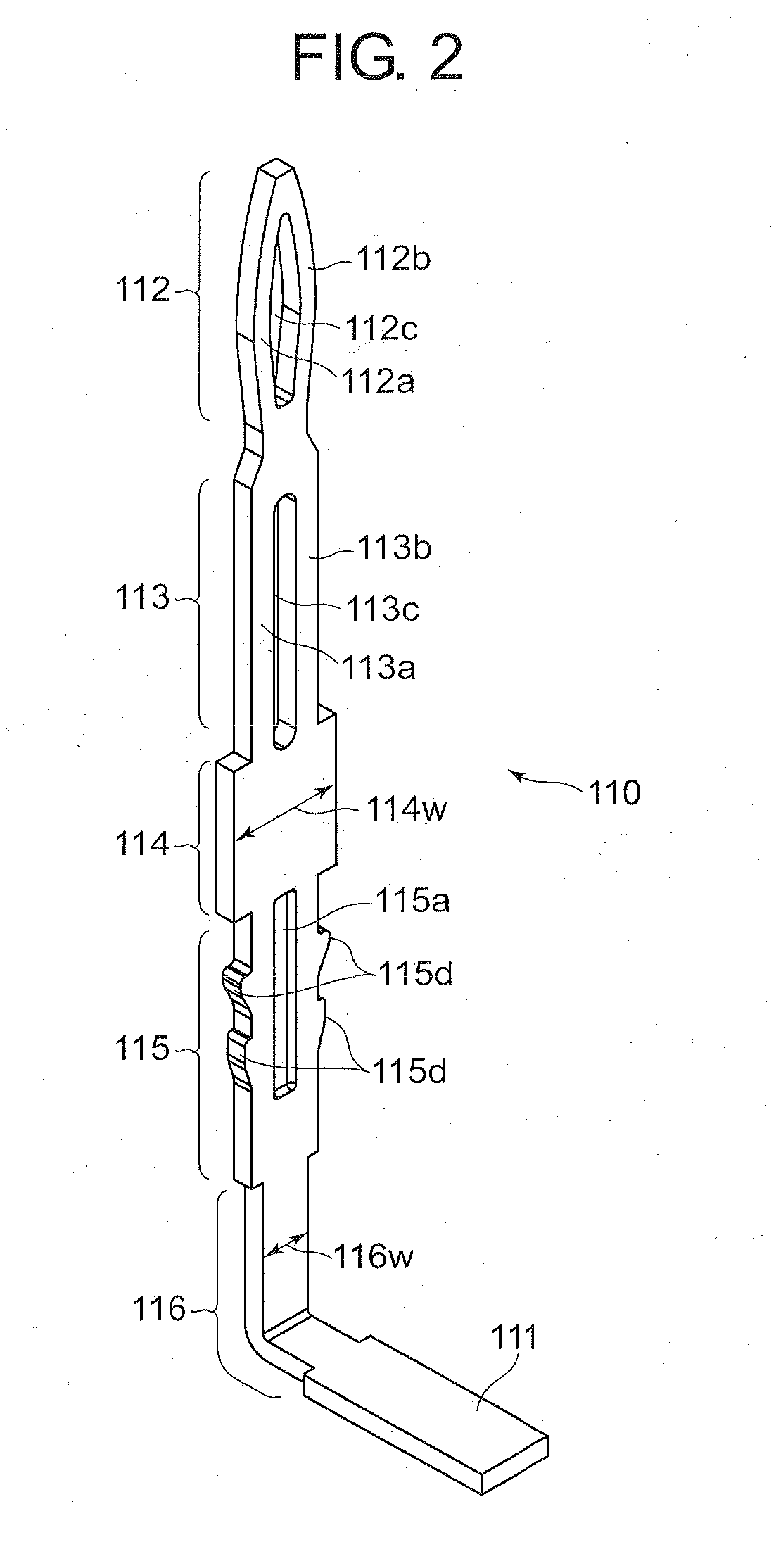
[0094]As illustrated in FIG. 6, the terminal module 100 is mounted onto a heat radiation board 10 through a frame 30 for electrically connecting a plurality of electric elements 20 fixed on the heat radiation board 10, to a circuit board 40 situated in facing relation with the heat radiation board 10 and formed with a plurality of through-holes 41. As illustrated in FIG. 1, the terminal module 100 includes at least one electrically conductive terminal 110 and electrically insulative base 130. The electrically conductive terminal 110 includes...

second embodiment

[0124]A terminal module 200 or 201 according to the second embodiment of the present invention is explained hereinbelow with reference to FIGS. 16 to 18.

[0125]Parts or elements in the terminal module 200 or 201 that correspond to those of the terminal module 100 illustrated in FIGS. 1 to 15 have been provided with the same reference numerals, operate in the same manner as corresponding parts or elements in the terminal module 200 or 201, unless explicitly explained hereinbelow, and are not explained hereinbelow.

[0126]As illustrated in FIG. 16, the terminal module 200 includes a plurality of electrically conductive terminals 11A, and a base 130A to which the electrically conductive terminals 11A are integrally fixed by an insertion molding process. The base 130A is formed integrally with a rib 138 extending in the direction S (see FIG. 1) to overlap a part of the connection part 111 of each of the electrically conductive terminals 11A.

[0127]As illustrated in FIG. 18, each of the elec...

third embodiment

[0131]A terminal module 300 according to the third embodiment of the present invention is explained hereinbelow with reference to FIGS. 19 to 30.

[0132]As illustrated in FIGS. 19, 24 and 28, the terminal module 300 includes a plurality of electrically conductive terminals 310, and an electrically insulative base 330. Each of the electrically conductive terminals 310 includes a connection part 111 through which the electrically conductive terminal 310 is electrically connected to the electric element 20, and a contact part 312 to be inserted into the through-hole 41 of the circuit board 40. The base 330 holds a part of the electrically conductive terminals 310 to keep the electrically conductive terminals 310 in a constant posture.

[0133]As illustrated in FIG. 20, each of the electrically conductive terminals 310 can be fabricated of an electrically conductive and elastic metal sheet through pressing and bending processes. Each of the electrically conductive terminals 310 is shaped sub...


PUM


Abstract

A terminal module is used for electrically connecting an electric element mounted on a first board to a second board opposing to the first board. A through-hole is opened in the second board. The terminal module includes: an electrically conductive terminal including at each of opposite ends thereof; a connection part through which the terminal module is electrically connected to the electric element; and a contact part to be inserted into the through-hole; and an electrically insulative base holding a part of the electrically conductive terminal to keep the electrically conductive terminal in a constant posture. The terminal module is mounted onto the first board keeping fixed thereto.

Description

BACKGROUND OF THE INVENTION[0001]1. Field of the Invention[0002]The present invention relates to a terminal module for electrically connecting electric elements mounted on a heat radiation board to an electrical circuit board in a power module to be equipped in an automobile, such as an engine control unit (ECU) and a power control unit (PCU).[0003]2. Description of the Related Art[0004]FIG. 68 is a perspective broken view of a conventional part unit.[0005]As illustrated in FIG. 68, a power module to be equipped in an automobile, such as an ECU and a PCU, is generally designed to include a part unit 900 including a heat radiation board 902 on which a plurality of electric elements 901 is mounted, a frame 904 on which a plurality of electrically conductive terminal 903 is mounted in a comb-like manner, and a circuit board 906 formed with a plurality of through-holes 905 and having electrical circuits (not illustrated) thereon. In the part unit 900, the electrically conductive termina...

Claims


Application Information

Patent Timeline
IPC IPC(8): H01R12/58
CPCH01R12/585H01R12/58H01R13/02H01R31/02H01L2224/48091H01L2224/48472H01R12/52H01R12/7082H05K3/308H01L2924/00014
Inventor ENDO, TAKAYOSHIYAGI, SAKAIKAKESE, KATSUNORITAKEDA, TAKUYAKURITA, HIROYUKI
Owner DAIICHI SEIKO CO LTD
Features
  • R&D
  • Intellectual Property
  • Life Sciences
  • Materials
  • Tech Scout
  • Unparalleled Data Quality
  • Higher Quality Content
  • 60% Fewer Hallucinations
Learn More